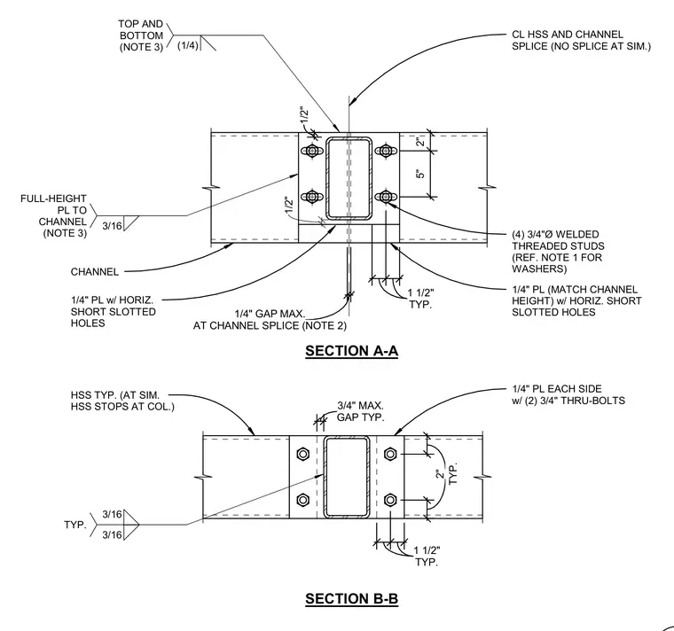
An HSS and channel splice with no splice at the similar condition incorporates a 1/4-inch plate matching the channel height with horizontal short slotted holes, connected by four 3/4-inch diameter welded threaded studs on the channel flanges. A 3/16-inch full-height plate secures the channel, complemented by a 1/4-inch maximum gap at the channel splice. Section B-B features a 1/4-inch plate on each side fastened with two 3/4-inch through-bolts and a 3/4-inch maximum typical gap. Top and bottom welds are specified at 1/4-inch size per engineering notes.
CL HSS AND CHANNEL SPLICE (NO SPLICE AT SIM.) 1/4" PL (MATCH CHANNEL HEIGHT) w/ HORIZ. SHORT SLOTTED HOLES 1/2" 5" 2" 3/16 FULL-HEIGHT PL TO CHANNEL (NOTE 3) CHANNEL (4) 3/4"Ø WELDED THREADED STUDS (REF. NOTE 1 FOR WASHERS) TYP. 1 1/2" TYP. 1 1/2" AT CHANNEL SPLICE (NOTE 2) 1/4" GAP MAX. SECTION A-A 1/4" PL EACH SIDE w/ (2) 3/4" THRU-BOLTS TYP. 2" TYP. 2" TYP. 1 1/2" TYP. 1 1/2" GAP TYP. 3/4" MAX. SECTION B-B HSS TYP. (AT SIM. HSS STOPS AT COL.) 3/16 3/16 TYP. 1/2" (1/4) TOP AND BOTTOM (NOTE 3) 1/4" PL w/ HORIZ. SHORT SLOTTED HOLES
Members view this detail in full resolution, download the CAD files (SVG, PDF), and can adapt it in the built-in CAD editor — export DXF, DWG, or PDF.
Start membership