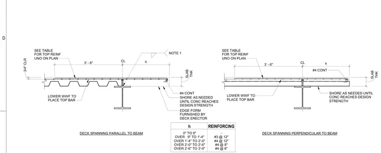
A concrete slab on metal deck is supported by wide flange steel beams, featuring continuous number four bottom reinforcing bars and welded wire fabric lowered to properly place top bars. An edge form furnished by the deck erector retains the concrete at the perimeter, with shoring installed as needed until the concrete reaches design strength. Additional top reinforcing bars are sized per the accompanying table based on distance h from the centerline of the support. A three-quarter-inch clear cover is maintained at the concrete edges.
THK SLAB 3' - 6" h DECK SPANNING PARALLEL TO BEAM DECK SPANNING PERPENDICULAR TO BEAM SEE TABLE FOR TOP REINF UNO ON PLAN LOWER WWF TO PLACE TOP BAR EDGE FORM FURNISHED BY DECK ERECTOR SHORE AS NEEDED UNTIL CONC REACHES DESIGN STRENGTH SHORE AS NEEDED UNTIL CONC REACHES DESIGN STRENGTH THK SLAB #4 CONT 3' - 6" h LOWER WWF TO PLACE TOP BAR #4 CONT h REINFORCING 0" TO 9" OVER 9" TO 1'-4" OVER 1'-4" TO 2'-0" OVER 2'-0" TO 2'-6" OVER 2'-6" TO 3'-0" - #3 @ 12" #4 @ 12" #4 @ 8" #4 @ 6" CL CL 3/4" CLR SEE TABLE FOR TOP REINF UNO ON PLAN NOTE 1 D
Members view this detail in full resolution, download the CAD files (SVG, PDF), and can adapt it in the built-in CAD editor — export DXF, DWG, or PDF.
Start membership