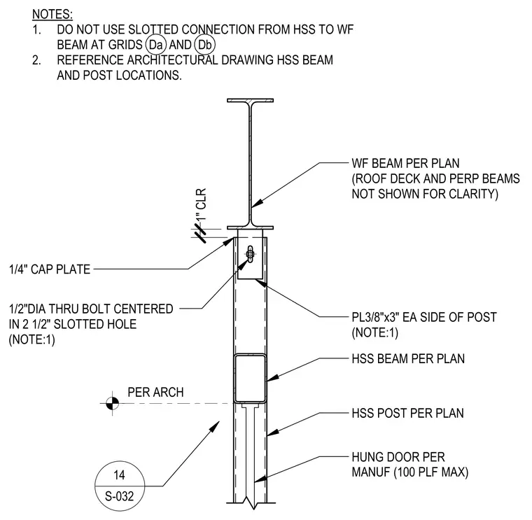
A wide-flange beam sits above a hollow structural section post with a one-inch clearance, welded to a quarter-inch cap plate. A half-inch diameter thru-bolt is centered in a two-and-a-half-inch slotted hole through three-eighths-inch thick plates on each side of the post. A hollow structural section beam frames into the post according to plan, supporting a hung door rated for one hundred pounds per linear foot maximum. A specific note restricts the use of slotted connections from the hollow structural section to the wide-flange beam at grids Da and Db.
WF BEAM PER PLAN (ROOF DECK AND PERP BEAMS NOT SHOWN FOR CLARITY) PL3/8"x3" EA SIDE OF POST (NOTE:1) HSS BEAM PER PLAN HSS POST PER PLAN HUNG DOOR PER MANUF (100 PLF MAX) NOTES: 1. DO NOT USE SLOTTED CONNECTION FROM HSS TO WF BEAM AT GRIDS Da AND Db 2. REFERENCE ARCHITECTURAL DRAWING HSS BEAM AND POST LOCATIONS. PER ARCH 1/4" CAP PLATE 1/2"DIA THRU BOLT CENTERED IN 2 1/2" SLOTTED HOLE (NOTE:1) 1" CLR 14 S-032
Members view this detail in full resolution, download the CAD files (SVG, PDF), and can adapt it in the built-in CAD editor — export DXF, DWG, or PDF.
Start membership