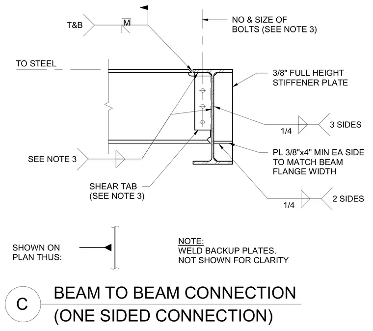
A supported steel beam connects to the web of a supporting steel beam using a bolted single-plate shear tab welded to the support. The supporting beam features three-eighth-inch full-height stiffener plates welded to the web with quarter-inch fillet welds on three sides, accompanied by three-eighth-inch by four-inch minimum plates on each side matching the beam flange width welded with quarter-inch fillet welds on two sides. Weld backup plates are welded in place but omitted from the drawing for clarity. The number and size of bolts and the shear tab dimensions are sized per the structural notes.
BEAM TO BEAM CONNECTION C (ONE SIDED CONNECTION) SHOWN ON PLAN THUS: TO STEEL NOTE: WELD BACKUP PLATES. NOT SHOWN FOR CLARITY NO & SIZE OF BOLTS (SEE NOTE 3) SHEAR TAB (SEE NOTE 3) 3/8" FULL HEIGHT STIFFENER PLATE PL 3/8"x4" MIN EA SIDE TO MATCH BEAM FLANGE WIDTH M T&B 1/4 3 SIDES SEE NOTE 3 1/4 2 SIDES
Members view this detail in full resolution, download the CAD files (SVG, PDF), and can adapt it in the built-in CAD editor — export DXF, DWG, or PDF.
Start membership