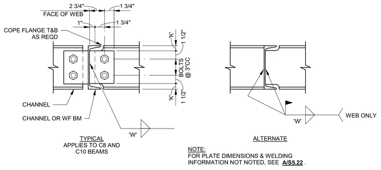
Channel and wide-flange beam connections apply to C8 and C10 members. The typical detail incorporates bolted connections through plates with specific edge distances and alternating bolt spacing at three inches center-to-center. Top and bottom flanges are coped as required to clear the intersecting member geometry. An alternate welded configuration incorporates field weld symbols along the web only, leaving flanges unwelded. Plate dimensions and additional welding specifications reference sheet A/S5.22.
CHANNEL OR WF BM TYPICAL APPLIES TO C8 AND C10 BEAMS ALTERNATE BOLTS @ 3"CC NOTE: FOR PLATE DIMENSIONS & WELDING INFORMATION NOT NOTED, SEE . COPE FLANGE T&B AS REQD CHANNEL 1" 1 3/4" 2 3/4" 1 3/4" 'K' 1 1/2" 1 1/2" 'K' 'W' 'W' WEB ONLY FACE OF WEB A/S5.22
Members view this detail in full resolution, download the CAD files (SVG, PDF), and can adapt it in the built-in CAD editor — export DXF, DWG, or PDF.
Start membership