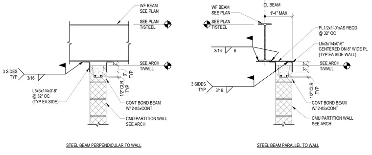
A concrete masonry unit partition wall connects to overhead steel wide-flange beams for both perpendicular and parallel orientations. The masonry wall terminates below a continuous reinforced concrete bond beam containing two continuous number five reinforcing bars, maintaining a typical one-half-inch clearance. For the perpendicular condition, an L5x3x1/4 angle measuring zero feet eight inches long is spaced at thirty-two inches on center on each side, welded to the underside of the beam flange with a three-sixteenth-inch fillet weld on three sides. For the parallel condition, a similar L5x3x1/4 angle measuring zero feet six inches long is centered on an eight-inch-wide plate at thirty-two inches on center on each side of the wall, attached with a three-sixteenth-inch fillet weld six inches long.
3/16 3 SIDES TYP L5x3x1/4x0'-8" @ 32" OC (TYP EA SIDE) CMU PARTITION WALL SEE ARCH WF BEAM SEE PLAN STEEL BEAM PERPENDICULAR TO WALL 3/16 3 SIDES TYP L5x3x1/4x0'-6" CENTERED ON 8" WIDE PL (TYP EA SIDE WALL) CMU PARTITION WALL SEE ARCH WF BEAM SEE PLAN STEEL BEAM PARALLEL TO WALL CL BEAM PL1/2x1'-0"xAS REQD @ 32" OC 3/16 6 TYP 1/2" CLR TYP 1/2" CLR CONT BOND BEAM W/ 2-#5xCONT CONT BOND BEAM W/ 2-#5xCONT SEE PLAN T/STEEL SEE PLAN T/STEEL SEE ARCH T/WALL SEE ARCH T/WALL 2" TYP 3" 3" 2" 1'-4" MAX
Members view this detail in full resolution, download the CAD files (SVG, PDF), and can adapt it in the built-in CAD editor — export DXF, DWG, or PDF.
Start membership