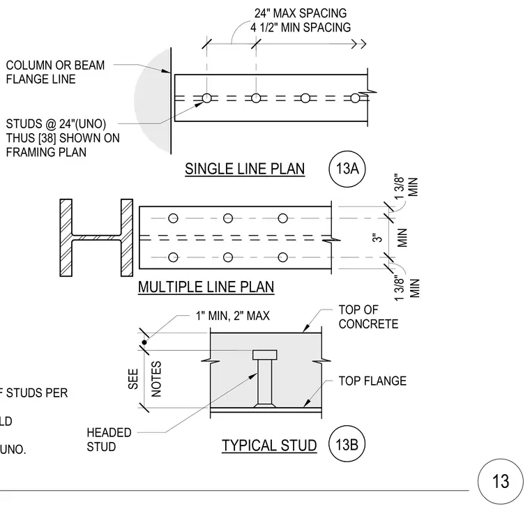
Headed shear studs are welded to the top flange of structural steel beams and columns to provide composite action with the concrete topping slab. Studs are spaced at twenty-four inches maximum on center unless noted otherwise, with minimum clearances of one and three-eighths inches from the flange edges and four and one-half inches between longitudinal rows. Studs extend upward into the concrete topping slab as far as standard lengths allow, maintaining a minimum cover of one inch and maximum of two inches to the top of concrete. Studs welded through metal decking may be substituted for typical plug welds, with stud counts increased at drag and frame beams per general structural notes.
SINGLE LINE PLAN MULTIPLE LINE PLAN TYPICAL STUD 1" MIN, 2" MAX HEADED STUD COLUMN OR BEAM FLANGE LINE STUDS @ 24"(UNO) THUS [38] SHOWN ON FRAMING PLAN TOP OF CONCRETE TOP FLANGE 4 1/2" MIN SPACING 24" MAX SPACING NOTES SEE MIN 3" STUDS AT 24" MAX AND 12" MAX AT DRAG AND FRAME BEAMS. INCREASE NUMBER OF STUDS PER 5. STUD WELDED THRU METAL DECKING MAY BE SUBSTITUTED FOR TYPICAL PLUG WELD 7. STUDS TO EXTEND AS FAR AS STANDARD STUD LENGTHS ALLOW IN TOPPING SLAB, UNO. MIN 1 3/8" MIN 1 3/8" 13A 13B 13
Members view this detail in full resolution, download the CAD files (SVG, PDF), and can adapt it in the built-in CAD editor — export DXF, DWG, or PDF.
Start membership