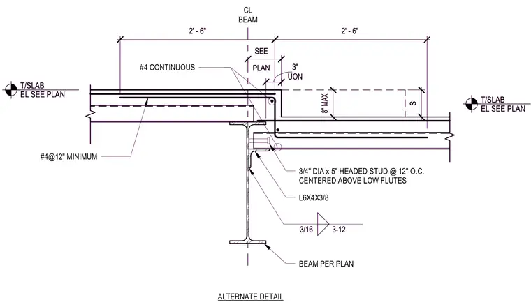
A concrete slab step bears on a steel beam sized per plan with a structural angle L6x4x3/8 welded underneath using a three-sixteenth-inch fillet weld at three inches on center with twelve-inch max spacing. Three-quarter-inch diameter by five-inch headed shear studs are welded to the top flange at twelve inches on center and centered above the low flutes. A continuous number four rebar runs along the slab step, complemented by number four bars spaced at twelve inches minimum unless otherwise noted. Top of slab elevations are sized per plan with a maximum eight-inch step height.
#4@12" MINIMUM CL BEAM UON 3" S 2' - 6" PLAN SEE 2' - 6" T/SLAB EL SEE PLAN T/SLAB EL SEE PLAN #4 CONTINUOUS 3/16 3-12 L6X4X3/8 8" MAX BEAM PER PLAN ALTERNATE DETAIL 3/4" DIA x 5" HEADED STUD @ 12" O.C. CENTERED ABOVE LOW FLUTES #4@12" MINIMUM CL BEAM UON 3" S 2' - 6" PLAN SEE 2' - 6" T/SLAB EL SEE PLAN T/SLAB EL SEE PLAN #4 CONTINUOUS 3/16 3-12 L6X4X3/8 8" MAX BEAM PER PLAN ALTERNATE DETAIL 3/4" DIA x 5" HEADED STUD @ 12" O.C. CENTERED ABOVE LOW FLUTES
Members view this detail in full resolution, download the CAD files (SVG, PDF), and can adapt it in the built-in CAD editor — export DXF, DWG, or PDF.
Start membership