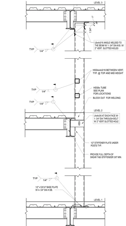
Vertical structural steel feature wall assembly spanning from Level 1 to Level 3 utilizing hollow structural section columns and horizontal framing members. The assembly consists of vertical HSS8x tubes positioned per plan with intermediate horizontal HSS4x4x5/16 tubes located at the top and mid-height of the post runs. The posts anchor at Level 1 to a one-half-inch by twelve-inch by fourteen-inch base plate secured with four three-quarter-inch diameter high-strength bolts and quarter-inch welds. Intermediate floor connections at Level 2 feature an L4x4x3/8 angle at each face connected with a three-quarter-inch diameter through bolt through a two-inch vertical slotted hole, alongside a one-half-inch stiffener plate and a minimum three-eighths-inch full-depth shear tab welded with quarter-inch fillet welds. The top connection at Level 3 incorporates an L6x4x5/16 angle welded to the supporting beam with a three-quarter-inch diameter machine bolt through a two-inch vertical slotted hole. Blockouts are provided at structural intersections to facilitate field welding.
LEVEL 2 HSS8x TUBE SEE PLAN FOR LOCATIONS HSS4x4x5/16 BETWEEN VERT. TYP. @ TOP AND MID HEIGHT 1/4" TYP BLOCK OUT FOR WELDING PROVIDE FULL DEPTH OF SHEAR TAB /STIFFENDER 3/8" MIN. 1/4" TYP 1/2" STIFFENER PLATE UNDER POSTS TYP. 1" 1 3/4" L6x4x5/16 ANGLE WELDED TO THE BEAM W/ 1- 3/4" DIA M.B. W/ 2" VERT. SLOTTED HOLES 1/4" TYP L4x4x3/8 AT EACH FACE W/ 1- 3/4" DIA THROUGH BOLT W/ 2" VERT SLOTTED HOLE LEVEL 3 LEVEL 1 1/2" x12X14" BASE PLATE W/ 4- 3/4" DIA H.SB. 1/4" TYP
Members view this detail in full resolution, download the CAD files (SVG, PDF), and can adapt it in the built-in CAD editor — export DXF, DWG, or PDF.
Start membership