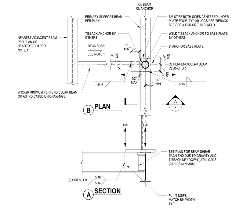
A tieback anchor connection frames into a primary support beam with a two-inch anchor base plate and perpendicular framing members. A W12x26 minimum perpendicular beam or header beam connects across the deck span. Beam stiffeners are welded to both sides centered under the plate edge with five-sixteenth-inch fillet welds on three sides typically. The primary support beam is designed for gravity and tieback up and down loads of twenty-five kips minimum, with a half-inch plate matching the beam width on near side and far side. Minimum clearances of four, five, and six inches are maintained between centerlines.
A - CL BEAM CL ANCHOR CL PERPENDICULAR BEAM CL ANCHOR MIN 6" MIN 5" MIN 4" MIN 4" W12X26 MINIMUM PERPENDICULAR BEAM OR AS INDICATED ON DRAWINGS NEAREST ADJACENT BEAM PER PLAN OR HEADER BEAM PER NOTE 1 WELD TIEBACK ANCHOR TO BASE PLATE BY OTHERS TIEBACK ANCHOR BY OTHERS 2" ANCHOR BASE PLATE PRIMARY SUPPORT BEAM PER PLAN SEE PLAN FOR BEAM SHEAR EACH END DUE TO GRAVITY AND TIEBACK UP / DOWN (U/D) LOADS (25 KIPS MINIMUM) U/D U/D DECK SPAN SEE NOTE 1 MIN 4" B PLAN A SECTION PL 1/2 NS/FS MATCH BM WIDTH TYP 5/16 5/16 (3) SIDES, TYP BM STIFF BOTH SIDES CENTERED UNDER PLATE EDGE. TYP (6) LOCS PER TIEBACK. SEE SEC A FOR SIZE AND WELD MAX 1/2" 5/16 5/16
Members view this detail in full resolution, download the CAD files (SVG, PDF), and can adapt it in the built-in CAD editor — export DXF, DWG, or PDF.
Start membership