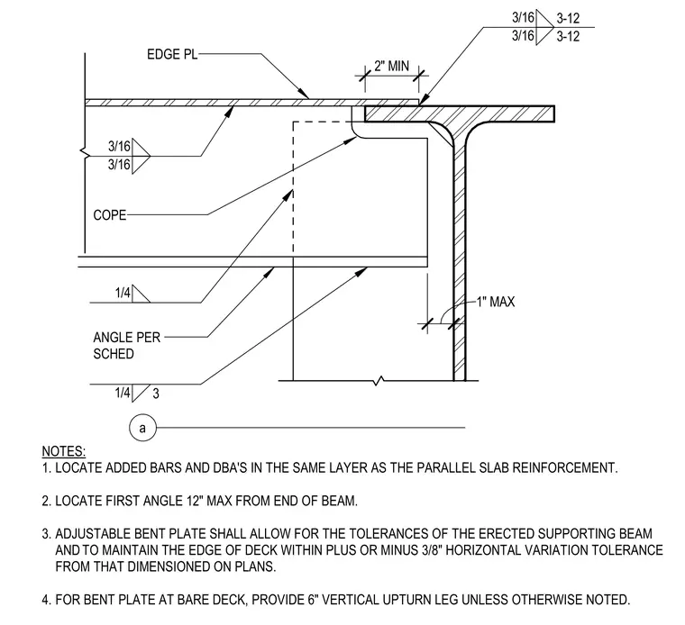
An edge plate is welded to the steel deck assembly with three-sixteenths inch fillet welds spaced at twelve inches. The supporting steel beam features a two-inch minimum cope and connects to an angle per schedule with a one-quarter inch fillet weld. The angle is positioned within a one-inch maximum distance from the face of the support web. Additional reinforcing bars and deformed bar anchors are located in the same layer as the parallel slab reinforcement. The adjustable bent plate accommodates erection tolerances of the supporting beam while maintaining the edge of deck within plus or minus three-eighths of an inch horizontal variation.
NOTES: 1. LOCATE ADDED BARS AND DBA'S IN THE SAME LAYER AS THE PARALLEL SLAB REINFORCEMENT. 2. LOCATE FIRST ANGLE 12" MAX FROM END OF BEAM. 3. ADJUSTABLE BENT PLATE SHALL ALLOW FOR THE TOLERANCES OF THE ERECTED SUPPORTING BEAM ANDTO MAINTAIN THE EDGE OF DECK WITHIN PLUS OR MINUS 3/8" HORIZONTAL VARIATION TOLERANCE FROM THAT DIMENSIONED ON PLANS. 4. FOR BENT PLATE AT BARE DECK, PROVIDE 6" VERTICAL UPTURN LEG UNLESS OTHERWISE NOTED. ANGLE PER SCHED 1/4 1/4 3 3/16 3-12 3/16 3-12 3/16 3/16 COPE 2" MIN EDGE PL 1" MAX a
Members view this detail in full resolution, download the CAD files (SVG, PDF), and can adapt it in the built-in CAD editor — export DXF, DWG, or PDF.
Start membership