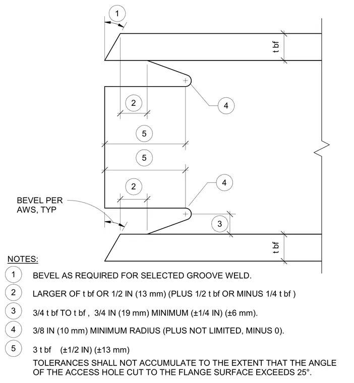
This structural steel detail defines the geometric parameters and dimensional tolerances for weld access holes cut into framing members. The configuration specifies a minimum radius of three-eighths of an inch at the base of the cut and establishes sizing relationships based on the flange thickness. Bevels are provided per American Welding Society standards to accommodate the selected groove weld. Cumulative tolerances must be controlled to prevent the angle of the access hole cut from exceeding twenty-five degrees relative to the flange surface.
NOTES: BEVEL AS REQUIRED FOR SELECTED GROOVE WELD. LARGER OF t bf OR 1/2 IN (13 mm) (PLUS 1/2 t bf OR MINUS 1/4 t bf ) 3/4 t bf TO t bf , 3/4 IN (19 mm) MINIMUM (±1/4 IN) (±6 mm). 3/8 IN (10 mm) MINIMUM RADIUS (PLUS NOT LIMITED, MINUS 0). 3 t bf (±1/2 IN) (±13 mm) TOLERANCES SHALL NOT ACCUMULATE TO THE EXTENT THAT THE ANGLE OF THE ACCESS HOLE CUT TO THE FLANGE SURFACE EXCEEDS 25°. 1 2 3 4 5 1 3 4 5 4 2 2 5 BEVEL PER AWS, TYP t bf t bf
Members view this detail in full resolution, download the CAD files (SVG, PDF), and can adapt it in the built-in CAD editor — export DXF, DWG, or PDF.
Start membership