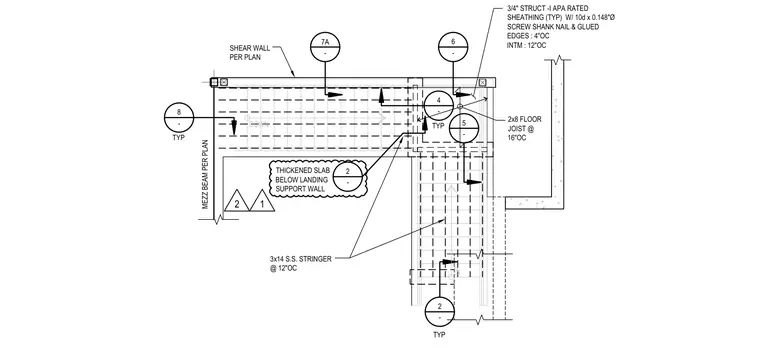
This structural plan details the wood framing layout for a stair landing and adjacent mezzanine floor. The assembly features three-by-four solid sawn stringers spaced at twelve inches on center supporting the stair run. Two-by-eight floor joists span at sixteen inches on center beneath the landing, framed into a mezzanine beam sized per plan. The floor platform is surfaced with three-quarter-inch Structural-I APA rated sheathing attached using ten-penny by zero-point-one-hundred-forty-eight-inch diameter screw shank nails and glued edges spaced at four inches on center for edges and twelve inches on center for intermediate supports. A shear wall per plan bounds the assembly, while a thickened concrete slab supports the landing support wall below.
7A - 4 - TYP 5 - 2x8 FLOOR JOIST @ 16"OC SHEAR WALL PER PLAN MEZZ BEAM PER PLAN 8 - TYP 2 - TYP 6 - 3x14 S.S. STRINGER @ 12"OC 3/4" STRUCT -I APA RATED SHEATHING (TYP) W/ 10d x 0.148"Ø SCREW SHANK NAIL & GLUED EDGES : 4"OC INTM : 12"OC UP DOWN 2 - THICKENED SLAB BELOW LANDING SUPPORT WALL 1 2
Members view this detail in full resolution, download the CAD files (SVG, PDF), and can adapt it in the built-in CAD editor — export DXF, DWG, or PDF.
Start membership