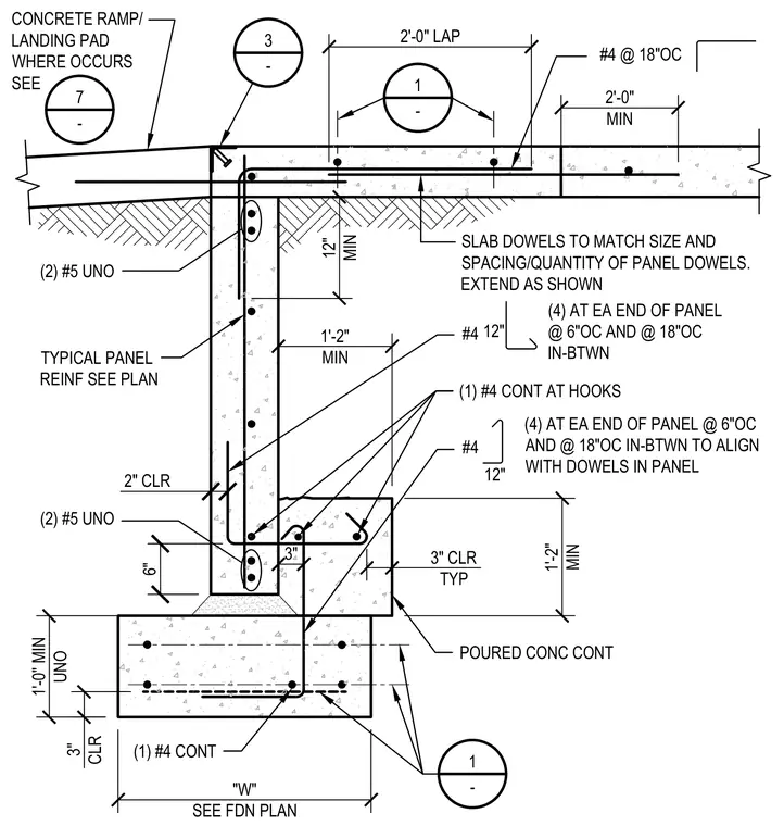
A poured concrete continuous footing supports a concrete foundation wall with specified reinforcing bars and concrete cover. Two number five bars run continuously unless noted otherwise, combined with number four bars at hooks and panel dowels placed at six inches on center at each end and eighteen inches on center in between. Slab dowels match the size, spacing, and quantity of the panel dowels with a two-foot minimum lap length. A concrete ramp or landing pad occurs at the top where indicated, featuring number four bars at eighteen inches on center. The footing width varies per the foundation plan with a minimum one-foot depth and three inches of clearance typical.
3" CLR TYP (1) #4 CONT AT HOOKS POURED CONC CONT 1'-2" MIN 12" #4 12" 1'-2" MIN 1'-0" MIN UNO 3" CLR (2) #5 UNO 2" CLR 6" 3" (4) AT EA END OF PANEL @ 6"OC AND @ 18"OC IN-BTWN TO ALIGN WITH DOWELS IN PANEL #4 (4) AT EA END OF PANEL @ 6"OC AND @ 18"OC IN-BTWN 1 - 1 - 2'-0" LAP 2'-0" MIN SLAB DOWELS TO MATCH SIZE AND SPACING/QUANTITY OF PANEL DOWELS. EXTEND AS SHOWN (2) #5 UNO TYPICAL PANEL REINF SEE PLAN CONCRETE RAMP/ LANDING PAD WHERE OCCURS SEE 7 - #4 @ 18"OC 12" MIN 3 - "W" SEE FDN PLAN (1) #4 CONT
Members view this detail in full resolution, download the CAD files (SVG, PDF), and can adapt it in the built-in CAD editor — export DXF, DWG, or PDF.
Start membership