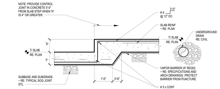
A concrete slab-on-grade step transition accommodates a maximum height 'H' of 1'-0". Number 5 reinforcing bars spaced at 12 inches on center reinforce the slab, with continuous number 5 reinforcing bars at the step transition for 'H' equal to or greater than 4 inches. A vapor barrier beneath the slab requires protection from puncture. A control joint is required in the concrete 5 feet from the slab step when 'H' is 4 inches or greater. The assembly rests on a prepared subbase and subgrade, with an underground drain adjacent to the thickened slab section.
SUBBASE AND SUBGRADE ~ RE: TYPICAL SOG JOINT DTL VAPOR BARRIER (IF REQD) ~ RE: SPECIFICATIONS AND ARCH DRAWINGS. PROTECT BARRIER FROM PUNCTURE 1'-0" 0'-6" 'T' 'H' # 5 @ 12" OC SLAB REINF ~ RE: PLAN NOTE: PROVIDE CONTROL JOINT IN CONCRETE 5'-0" FROM SLAB STEP WHEN 'H' IS 4" OR GREATER. # 5 x CONT NOTE: PROVIDE SLAB STEP REINF BARS ONLY AT LOCATIONS WHERE 'H' IS 4" OR GREATER. 'H' = 1'-0" MAX T/ SLAB RE: PLAN T/ SLAB RE: PLAN TYPICAL THICKENED SLAB 1-#5 CONT EACH SIDE OF WALL VAPOR BARRIER (IF REQD) ~ RE: SPECIFICATIONS AND ARCH DRAWINGS. PROTECT BARRIER FROM PUNCTURE SLAB REINF ~ RE: PLAN 0'-4" 'T' 0'-4" 9" MIN NOTE: 'T' DENOTES STAIR STRINGER BEARING WIDTH 3'-0" UNDERGROUND DRAIN RE: CIVIL UNDERGROUND DRAIN RE: CIVIL
Members view this detail in full resolution, download the CAD files (SVG, PDF), and can adapt it in the built-in CAD editor — export DXF, DWG, or PDF.
Start membership