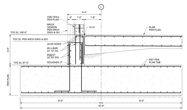
A concrete foundation wall supports a concrete masonry unit wall with an exterior brick veneer and an adjacent concrete slab. The foundation wall contains vertical reinforcement with number five U-bars spaced at twelve inches on center and two number five horizontal bars at the top. A roughened construction joint is specified between the foundation wall and the lower slab. An expansion joint is located between the concrete masonry unit wall and the suspended slab. Reinforcing steel is placed top and bottom in the slabs per plan.
L TOC EL 100'-0" 8" 1'-0" 1'-8" 3'-4" 8'-0" 8'-0" 16'-0" 3'-0" PER PLAN #5 U-BAR AT 12" OC ROUGHEN JT #5@12" OC EF EW #5@12" OC EF EW RST PER PLAN T&B RST PER PLAN T&B EJ-H SLAB PER PLAN (2) #5 HORIZ BRICK VENEER PER ARCH DWG A-351 CMU WALL PER PLAN TOC EL 97'-0" TOC EL PER ARCH DWG A-203
Members view this detail in full resolution, download the CAD files (SVG, PDF), and can adapt it in the built-in CAD editor — export DXF, DWG, or PDF.
Start membership