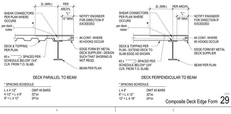
These structural details illustrate composite metal deck and concrete slab edges supported by structural steel beams, showing both parallel and perpendicular deck configurations. An edge form supplied by the metal deck manufacturer is positioned at the slab perimeter with a design requiring no shoring. Shear connectors are placed along the top flange of the steel beam as specified per plan. Reinforcing includes continuous number four bars where number three hooks occur, along with number three bars spaced per the provided overhang spacing schedule maintaining three-quarters of an inch clearance from the top of the slab.
DECK PARALLEL TO BEAM DECK PERPENDICULAR TO BEAM DECK & TOPPING PER PLAN SHEAR CONNECTORS PER PLAN WHERE OCCURS #4 CONT. WHERE #3 HOOKS OCCUR NOTIFY ENGINEER FOR DIRECTION IF EXCEEDED EDGE FORM BY METAL DECK SUPPLIER - DESIGN SUCH THAT SHORING IS NOT REQD. BEAM PER PLAN DECK & TOPPING PER PLAN - EXTEND DECK TO SLAB EDGE AS SHOWN EDGE FORM BY METAL DECK SUPPLIER L ≤ 4 1/2" 4 1/2" < L ≤ 8" 8" < L ≤ 12" OMIT #3 BARS 32"oc 24"oc * SPACING SCHEDULE L ≤ 6" 6" < L ≤ 12" 12" < L ≤ 18" OMIT #3 BARS 32"oc 24"oc * SPACING SCHEDULE #3 x SPACED PER SCHEDULE BELOW* (3/4" CLR. FROM T.O. SLAB) BEAM PER PLAN per deck notes per deck notes SHEAR CONNECTORS PER PLAN WHERE OCCURS #4 CONT. WHERE #3 HOOKS OCCUR NOTIFY ENGINEER FOR DIRECTION IF EXCEEDED #3 x SPACED PER SCHEDULE BELOW* (3/4" CLR. FROM T.O. SLAB) 2L (MIN.) ARCH'L PER 12" MAX. "L" 18" MAX. "L" 2L (MIN.) PER ARCH'L 4 5 29 Composite Deck Edge Form 5015
Members view this detail in full resolution, download the CAD files (SVG, PDF), and can adapt it in the built-in CAD editor — export DXF, DWG, or PDF.
Start membership