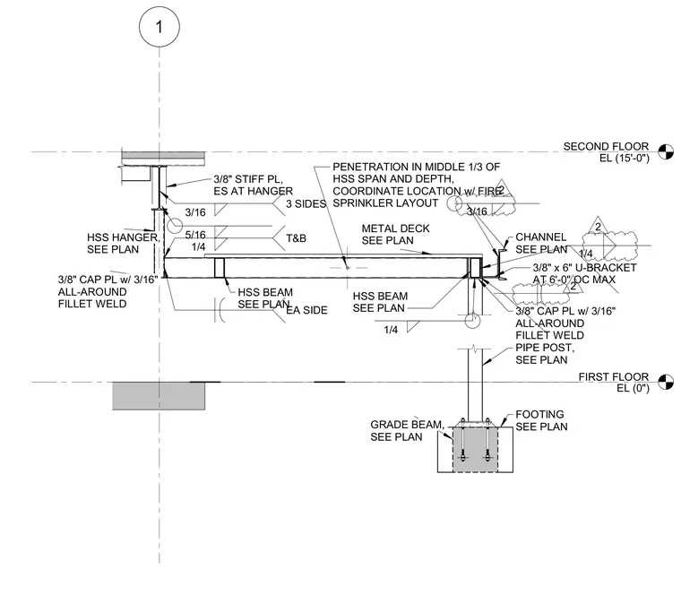
This structural section shows a steel canopy framing assembly tied back to the second floor and supported at the exterior edge by a pipe post on a grade beam and footing. The hollow structural section hanger connects to the overhead structure with three-eighths-inch stiffener plates welded on each side using three-sixteenths-inch fillet welds. The canopy roof framing incorporates hollow structural section beams sized per plan supporting metal deck and a channel edge member, with a three-eighths-inch cap plate welded all around. A pipe post sits on a three-eighths-inch cap plate at the base and bears on a concrete footing and grade beam assembly. U-brackets measuring three-eighths by six inches are spaced at six feet on center maximum along the edge.
FIRST FLOOR EL (0") SECOND FLOOR EL (15'-0") 1 3/8" STIFF PL, ES AT HANGER 3/16 3 SIDES 5/16 HSS HANGER, SEE PLAN 3/8" CAP PL w/ 3/16" ALL-AROUND FILLET WELD 1/4 T&B HSS BEAM SEE PLAN PENETRATION IN MIDDLE 1/3 OF HSS SPAN AND DEPTH, COORDINATE LOCATION w/ FIRE SPRINKLER LAYOUT HSS BEAM SEE PLAN METAL DECK SEE PLAN CHANNEL SEE PLAN 3/8" CAP PL w/ 3/16" ALL-AROUND FILLET WELD PIPE POST, SEE PLAN 1/4 FOOTING SEE PLAN GRADE BEAM, SEE PLAN EA SIDE 3/8" x 6" U-BRACKET AT 6'-0" OC MAX 3/16 1/4 2 2 2
Members view this detail in full resolution, download the CAD files (SVG, PDF), and can adapt it in the built-in CAD editor — export DXF, DWG, or PDF.
Start membership