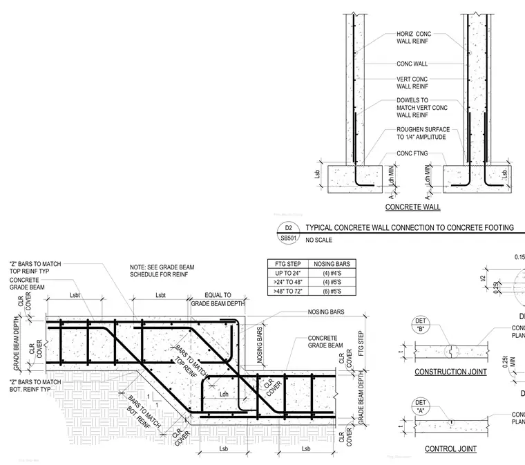
A concrete wall connects to a continuous concrete footing via vertical dowels matching the wall reinforcement and a roughened surface interface to one-quarter-inch amplitude. The footing provides specified lap splice lengths and minimum hook development lengths for the dowels. Horizontal wall reinforcement continues through the vertical wall section above the cold joint.
MIN 0.25t 0.25t 0.15t t/2 CONTROL JOINT CONSTRUCTION JOINT CONCRETE SLAB SEE PLANS FOR THICKNESS DETAIL "A" "A" DET DETAIL "B" "B" DET CONCRETE SLAB SEE PLANS FOR THICKNESS t t Ftng-Slab-Details Ftng-Step-Mat CONCRETE GRADE BEAM "Z" BARS TO MATCH BOT. REINF TYP 1 1 GRADE BEAM DEPTH COVER CLR GRADE BEAM DEPTH EQUAL TO Lsbt GRADE BEAM DEPTH FTG STEP COVER CLR NOSING BARS NOSING BARS BOT. REINF BARS TO MATCH CONCRETE GRADE BEAM NOTE: SEE GRADE BEAM SCHEDULE FOR REINF FTG STEP NOSING BARS UP TO 24" (4) #4'S >24" TO 48" (4) #5'S >48" TO 72" (6) #5'S COVER CLR TOP REINF BARS TO MATCH Lsb Lsbt COVER CLR COVER CLR COVER CLR "Z" BARS TO MATCH TOP REINF TYP Lsb Ldh Ftng-Wall-to-Footing CONCRETE WALL CONC WALL VERT CONC WALL REINF HORIZ CONC WALL REINF DOWELS TO MATCH VERT CONC WALL REINF CONC FTNG ROUGHEN SURFACE TO 1/4" AMPLITUDE Ldh MIN Ldh MIN Lsb Lsb A A NO SCALE SB501 D2 TYPICAL CONCRETE WALL CONNECTION TO CONCRETE FOOTING
Members view this detail in full resolution, download the CAD files (SVG, PDF), and can adapt it in the built-in CAD editor — export DXF, DWG, or PDF.
Start membership