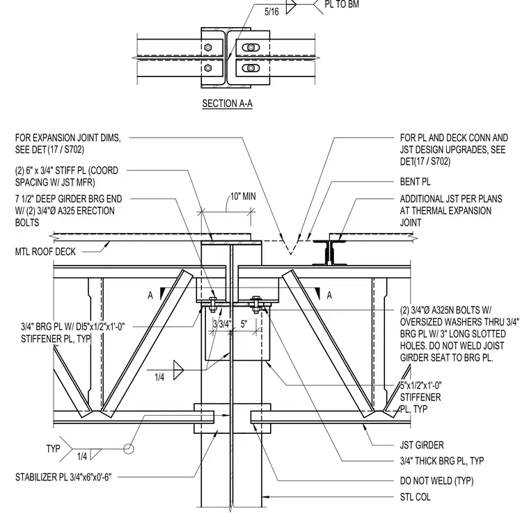
A thermal expansion joint at a steel column supports joist girders and metal roof decking. A three-quarter-inch bearing plate with a five-by-one-half-inch by one-foot stiffener plate connects to the steel column and supports the joist girder end using two three-quarter-inch diameter A325N bolts with oversized washers through three-inch long slotted holes, left unwelded to the girder seat. Two six-by-three-quarter-inch stiffener plates and three-quarter-inch by six-inch by zero-foot-six-inch stabilizer plates are detailed on the column. Additional joist girders and metal roof decking span across the assembly per plans, with specific dimensions and plate connections referenced to another sheet.
A A DO NOT WELD (TYP) JST GIRDER STABILIZER PL 3/4"x6"x0'-6" ADDITIONAL JST PER PLANS AT THERMAL EXPANSION JOINT 7 1/2" DEEP GIRDER BRG END W/ (2) 3/4"Ø A325 ERECTION BOLTS MTL ROOF DECK TYP 1/4 STL COL BENT PL (2) 6" x 3/4" STIFF PL (COORD SPACING W/ JST MFR) (2) 3/4"Ø A325N BOLTS W/ OVERSIZED WASHERS THRU 3/4" BRG PL W/ 3" LONG SLOTTED HOLES. DO NOT WELD JOIST GIRDER SEAT TO BRG PL. 3/4" BRG PL W/ DI5"x1/2"x1'-0" STIFFENER PL, TYP 10" MIN 5" 3 3/4" SECTION A-A 5"x1/2"x1'-0" STIFFENER PL, TYP 3/4" THICK BRG PL, TYP 5/16 PL TO BM 1/4 FOR PL AND DECK CONN AND JST DESIGN UPGRADES, SEE DET / (17 S702) FOR EXPANSION JOINT DIMS, SEE DET / (17 S702)
Members view this detail in full resolution, download the CAD files (SVG, PDF), and can adapt it in the built-in CAD editor — export DXF, DWG, or PDF.
Start membership