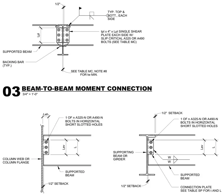
This structural steel detail shows a moment connection between a supported beam and a supporting beam or girder, or a column web or flange. The supported beam frames into the supporting member using single shear plates on each side, fastened with ASTM A325 or A490 slip-critical bolts in horizontal short slotted holes. A backing bar is typical at the top and bottom flange welds, with a one-half inch setback maintained between members. Connection plate dimensions and thicknesses are sized per the referenced tables on the engineering drawings.
COLUMN WEB OR COLUMN FLANGE L 1/2" SETBACK Lev Leh SUPPORTED BEAM 1 OF n A325-N OR A490-N BOLTS IN HORIZONTAL SHORT SLOTTED HOLES 1/2" SETBACK 1/2" SETBACK L Lev SUPPORTED BEAM SUPPORTING BEAM OR GIRDER 1 OF n A325-N OR A490-N BOLTS IN HORIZONTAL SHORT SLOTTED HOLES CONNECTION PLATE SEE TABLE SP FOR t AND L W W tpl x 4" x Lpl SINGLE SHEAR PLATE EACH SIDE W/ SLIP CRITICAL A325 OR A490 BOLTS (SEE TABLE MC) BACKING BAR (TYP.) TYP. TOP & BOTT., EACH SIDE 1/2" FOR tw MIN. SEE TABLE MC, NOTE #8 SUPPORTED BEAM Lpl 3/4" = 1'-0" 03 BEAM-TO-BEAM MOMENT CONNECTION
Members view this detail in full resolution, download the CAD files (SVG, PDF), and can adapt it in the built-in CAD editor — export DXF, DWG, or PDF.
Start membership