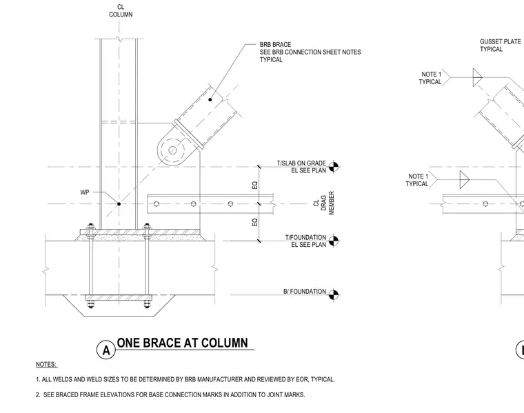
A buckling-restrained brace connects to a steel column and a horizontal drag member via a gusset plate centered at the work point. The column base plate transfers loads to anchor bolts extending into the foundation. All welds and weld sizes are determined by the buckling-restrained brace manufacturer and reviewed by the engineer of record. Additional base connection marks and joint marks are coordinated with the braced frame elevations.
CL COLUMN EL SEE PLAN T/SLAB ON GRADE EL SEE PLAN T/FOUNDATION B/ FOUNDATION EQ EQ CL DRAG MEMBER WP A ONE BRACE AT COLUMN NOTES: 1. ALL WELDS AND WELD SIZES TO BE DETERMINED BY BRB MANUFACTURER AND REVIEWED BY EOR, TYPICAL. 2. SEE BRACED FRAME ELEVATIONS FOR BASE CONNECTION MARKS IN ADDITION TO JOINT MARKS. B BRB BRACE SEE BRB CONNECTION SHEET NOTES TYPICAL GUSSET PLATE TYPICAL NOTE 1 TYPICAL NOTE 1 TYPICAL
Members view this detail in full resolution, download the CAD files (SVG, PDF), and can adapt it in the built-in CAD editor — export DXF, DWG, or PDF.
Start membership