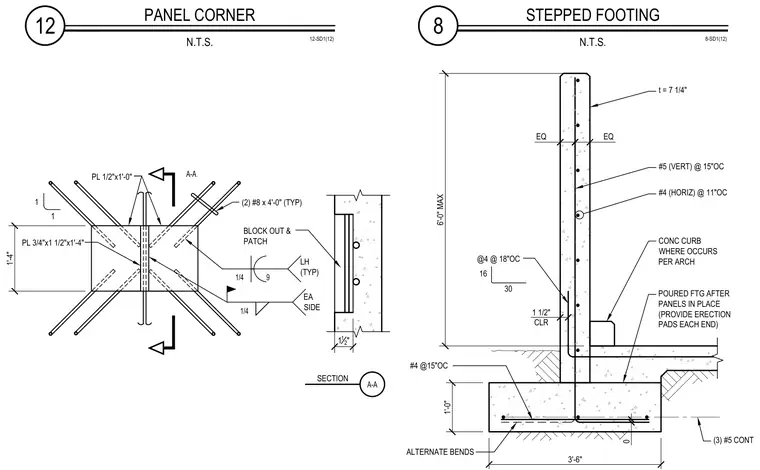
The panel corner connection features a three-quarter-inch by one-and-a-half-inch by one-foot-four-inch plate welded to half-inch by one-foot plates with quarter-inch fillet welds, reinforced by two number eight by four-foot dowels typically on each side. The stepped concrete footing detail shows a seven-and-a-quarter-inch thick concrete wall supported by a three-foot-six-inch wide footing poured after panels are placed with erection pads at each end. Vertical reinforcement consists of number five bars at fifteen inches on center, and horizontal reinforcement consists of number four bars at eleven inches on center. The footing includes three continuous number five bars with alternate bends, number four bars at fifteen inches on center, and a concrete curb blocked out and patched per architectural requirements.
8 STEPPED FOOTING N.T.S. 8-SD1(12) 12 PANEL CORNER N.T.S. 12-SD1(12) 3'-6" 0 1'-0" 6'-0" MAX EQ EQ (3) #5 CONT ALTERNATE BENDS #4 @15"OC t = 7 1/4" #5 (VERT) @ 15"OC #4 (HORIZ) @ 11"OC POURED FTG AFTER PANELS IN PLACE (PROVIDE ERECTION PADS EACH END) 1 12 " 1'-4" LH (TYP) EA SIDE 1/4 1/4 9 A-A A-A SECTION 1 1 PL 3/4"x1 1/2"x1'-4" PL 1/2"x1'-0" (2) #8 x 4'-0" (TYP) BLOCK OUT & PATCH CONC CURB WHERE OCCURS PER ARCH @4 @ 18"OC 16 30 1 1/2" CLR
Members view this detail in full resolution, download the CAD files (SVG, PDF), and can adapt it in the built-in CAD editor — export DXF, DWG, or PDF.
Start membership