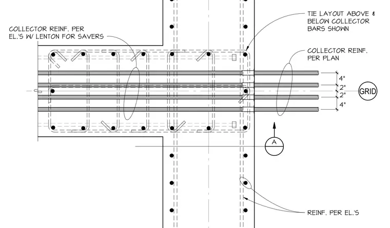
Continuous collector reinforcement passes through the concrete member with mechanical splices utilizing Lenton threaded couplers. Reinforcement spacing is detailed at four inches, two inches, two inches, and four inches relative to the grid line. Additional tie layouts are positioned above and below the collector bars as specified per the structural plan. Standard longitudinal and transverse reinforcing bars are detailed throughout the concrete section.
GRID 4" 2" 2" 4" A COLLECTOR REINF. PER PLAN TIE LAYOUT ABOVE & BELOW COLLECTOR BARS SHOWN COLLECTOR REINF. PER EL.'S W/ LENTON FOR SAVERS REINF. PER EL.'S
Members view this detail in full resolution, download the CAD files (SVG, PDF), and can adapt it in the built-in CAD editor — export DXF, DWG, or PDF.
Start membership