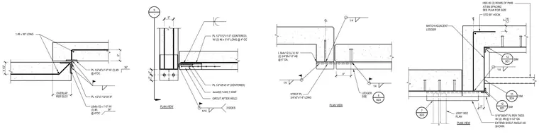
Precast concrete wall panels and ledgers are joined using embedded steel plates, structural angles, and welded connections reinforced with anchor bolts and dowels. Steel plates measuring 1/2 inch thick by 12 inches by 1 foot are centered with three number 6 reinforcing bars at 4 inches on center. Additional connection assemblies utilize L 8x4x1/2 angles with two 3/4-inch diameter by 1-foot anchor bolts at 6-inch gauge, complemented by strut plates and welded wire reinforcement. Voids at welded connections are grouted solid after welding. Reinforcing dowels include number 5 bars at 36 inches long overlapping per elevations.
1/4 PLAN VIEW 5/16" BENT PL PER 7/SD3 W/ (2) #6 @ 5 1/2" GA 3" CLR STD 90° HOOK MATCH ADJACENT LEDGER 10 SD4 SIM 12 SD1 SIM 12 SD1 SIM HSS W/ (2) ROWS OF PINS AT BN SPACING SEE PLAN FOR SIZE 3" 7 SD3 JOIST SEE PLAN EXTEND SHELF ANGLE AS SHOWN 8" CL LEDGER SEE PLAN VIEW STRUT PL 3/4"x3"x1'-8" LONG 1/4 L 8x4x1/2 (LLV) W/ (2) 3/4"Øx1'-0" AB @ 6" GA. 1/4 1/4 8 SD3 5" 3" 3" PL 1/2"X12"x1'-0" (CENTERED) W/ (3) #6 x 5'-0" LONG @ 4" OC PL 1/2"x8"x0'-8" (CENTERED) 5/16 3 SIDES GROUT AFTER WELD 4x4xW2.1xW2.1 WWF PLAN VIEW 9 - 6" 6 1/2" OVERLAP PER ELEV 1 #5 x 36" LONG PL 1/2"x6"x1'-0" W/ (3) #5 @ 4"OC 36" PL 1/2"x3 1/2"x0'-8" L6x6x1/2 x 1'-0" W/ (3) #5 @ 4"OC 36"
Members view this detail in full resolution, download the CAD files (SVG, PDF), and can adapt it in the built-in CAD editor — export DXF, DWG, or PDF.
Start membership