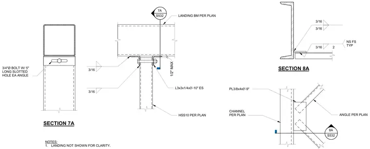
An HSS10 column connects to a landing beam sized per plan using clip angles and slotted bolt holes to allow lateral adjustment. The connection features two L3x3x1/4-inch angles each measuring zero feet ten inches long, secured with three-quarter-inch diameter bolts through five-inch long slotted holes in each angle. Fillet welds of three-sixteenths inch size connect the angles to the members. A secondary connection detail shows a channel member joined to an angle with a three-eighths by four-inch plate measuring zero feet nine inches long. The landing is omitted from the main view for clarity, maintaining a maximum half-inch clearance gap.
SECTION 8A S532 8A CHANNEL PER PLAN PL3/8x4x0'-9" ANGLE PER PLAN 3/16 3/16 3/16 2 NS FS TYP NOTES: 1. LANDING NOT SHOWN FOR CLARITY. LANDING BM PER PLAN HSS10 PER PLAN 3/16 3/16 L3x3x1/4x0'-10" ES S532 7A SECTION 7A 3/4"Ø BOLT W/ 5" LONG SLOTTED HOLE EA ANGLE 1/2" MAX
Members view this detail in full resolution, download the CAD files (SVG, PDF), and can adapt it in the built-in CAD editor — export DXF, DWG, or PDF.
Start membership