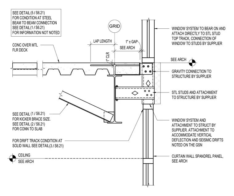
A perimeter floor and spandrel condition consists of a concrete slab over a metal floor deck bearing on a wide-flange steel beam. A steel stud framing member and gravity connection are tied back to the structural steel framework, designed to accommodate vertical deflection and seismic drifts. A kicker brace connects diagonally to the underside of the floor beam, while the exterior window system and curtain wall spandrel panel attach directly to the steel stud top track. Clearances and lap lengths are explicitly noted at the slab edge alongside references to architectural and structural companion details.
CEILING SEE ARCH GRID WINDOW SYSTEM TO BEAR ON AND ATTACH DIRECTLY TO STL STUD TOP TRACK, CONNECTION OF WINDOW TO STUDS BY SUPPLIER GRAVITY CONNECTION TO STRUCTURE BY SUPPLIER STL STUDS AND ATTACHMENT TO STRUCTURE BY SUPPLIER CURTAIN WALL SPANDREL PANEL, SEE ARCH WINDOW SYSTEM AND ATTACHMENT TO STRUCT BY SUPPLIER. ATTACHMENT TO ACCOMMODATE VERTICAL DEFLECTION AND SEISMIC DRIFTS NOTED ON THE GSN CONC OVER MTL FLR DECK SEE DETAIL FOR KICKER BRACE SIZE. SEE DETAIL FOR CONN TO SLAB FOR DRIFT TRACK CONDITION AT SOLID WALL SEE DETAIL SEE DETAIL FOR CONDITION AT STEEL BEAM TO BEAM CONNECTION SEE DETAIL FOR INFORMATION NOT NOTED SEE ARCH 1" ± GAP SEE ARCH LAP LENGTH 1" CLR / (5 S6.21) / (1 S6.21) / (1 S6.21) / (2 S6.21) / (3 S6.21)
Members view this detail in full resolution, download the CAD files (SVG, PDF), and can adapt it in the built-in CAD editor — export DXF, DWG, or PDF.
Start membership