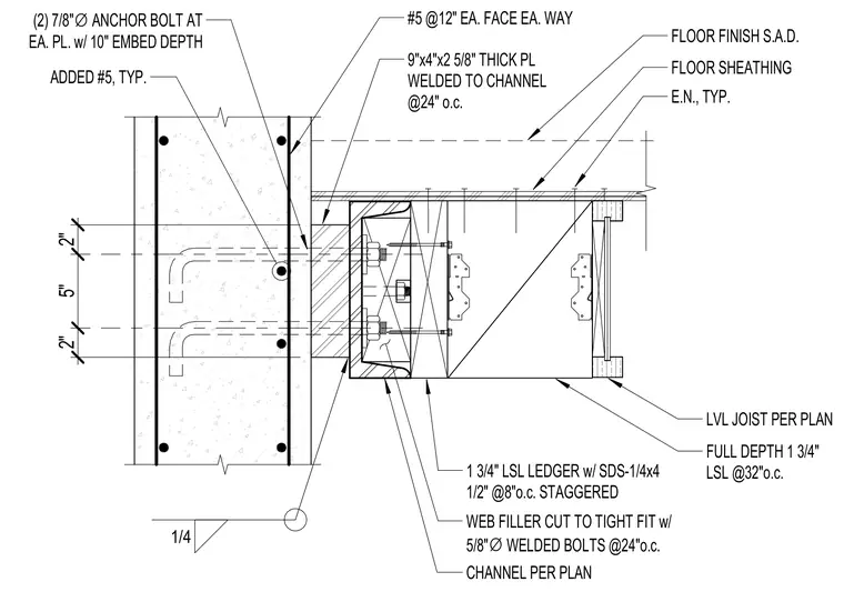
A wood floor framing connection bears against a reinforced concrete wall. A steel channel per plan is anchored to the concrete wall via a nine-by-four by two-and-five-eighths-inch thick plate welded to the channel at twenty-four inches on center. The concrete wall is reinforced with number five reinforcing bars at twelve inches each face each way, plus added number five bars, and two seven-eighths-inch diameter anchor bolts at each plate with a ten-inch embedment depth. Inside the channel, a web filler is cut to a tight fit with five-eighths-inch diameter welded bolts at twenty-four inches on center. A one-and-three-quarter-inch laminated strand lumber ledger is fastened with quarter-inch by four-and-one-half-inch SDS screws at eight inches on center staggered. Floor framing consists of laminated veneer lumber joists per plan with full-depth one-and-three-quarter-inch laminated strand lumber at thirty-two inches on center, supporting floor sheathing and floor finish.
LVL JOIST PER PLAN E.N., TYP. FLOOR SHEATHING FLOOR FINISH S.A.D. FULL DEPTH 1 3/4" LSL @32"o.c. 1 3/4" LSL LEDGER w/ SDS-1/4x4 1/2" @8"o.c. STAGGERED CHANNEL PER PLAN WEB FILLER CUT TO TIGHT FIT w/ 5/8" ∅ WELDED BOLTS @24"o.c. 9"x4"x2 5/8" THICK PL WELDED TO CHANNEL @24" o.c. 1/4 2" 5" 2" #5 @12" EA. FACE EA. WAY ADDED #5, TYP. (2) 7/8" ∅ ANCHOR BOLT AT EA. PL. w/ 10" EMBED DEPTH
Members view this detail in full resolution, download the CAD files (SVG, PDF), and can adapt it in the built-in CAD editor — export DXF, DWG, or PDF.
Start membership