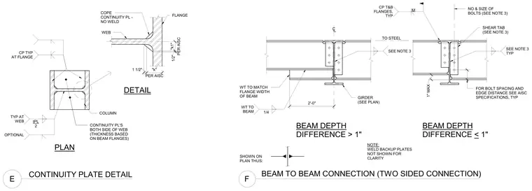
Two-sided beam-to-beam connection details illustrate framing conditions for both beam depth differences greater than one inch and differences less than or equal to one inch, featuring shear tabs sized per plan and welded connections with a quarter-inch fillet weld. A separate continuity plate detail shows structural steel column web and flange copes with continuity plates provided on both sides of the web, with plate thickness based on the beam flanges and weld configurations per AISC specifications. Bolt spacing and edge distances follow standard AISC guidelines.
BEAM TO BEAM CONNECTION (TWO SIDED CONNECTION) F BEAM DEPTH DIFFERENCE > 1" BEAM DEPTH DIFFERENCE < 1" NOTE: WELD BACKUP PLATES NOT SHOWN FOR CLARITY TO STEEL NO & SIZE OF BOLTS (SEE NOTE 3) FOR BOLT SPACING AND EDGE DISTANCE SEE AISC SPECIFICATIONS, TYP SHEAR TAB (SEE NOTE 3) GIRDER (SEE PLAN) WT TO MATCH FLANGE WIDTH OF BEAM SHOWN ON PLAN THUS: 2'-0" 1/4 WT TO BEAM SEE NOTE 3 1" MAX . CP T&B FLANGES, TYP SEE NOTE 3 TYP M DETAIL PLAN CONTINUITY PLATE DETAIL E COLUMN WEB FLANGE COPE CONTINUITY PL - NO WELD 1/2" PER AISC "k1" 1 1/2" PER AISC "k" CONTINUITY PL'S BOTH SIDE OF WEB (THICKNESS BASED ON BEAM FLANGES) OPTIONAL TYP AT WEB tPL 2 CP TYP AT FLANGE
Members view this detail in full resolution, download the CAD files (SVG, PDF), and can adapt it in the built-in CAD editor — export DXF, DWG, or PDF.
Start membership