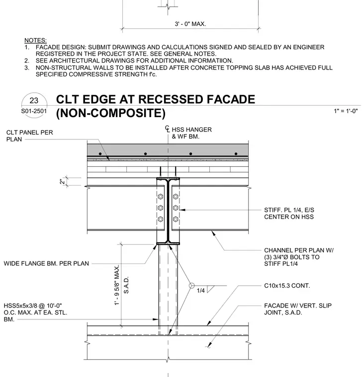
A cross-laminated timber panel floor edge at a recessed non-composite facade is supported by a wide flange beam and a hollow structural section hanger spaced at a maximum of ten feet on center at each steel beam. A continuous C10x15.3 channel connects to a one-quarter-inch stiffener plate on each side centered on the hollow structural section using three three-quarter-inch diameter bolts. A facade with a vertical slip joint is installed below the steel channel. General notes mandate that facade designs be submitted with engineer-signed calculations and that non-structural walls be installed only after the concrete topping slab achieves full specified compressive strength.
NOTES: 1. FACADE DESIGN: SUBMIT DRAWINGS AND CALCULATIONS SIGNED AND SEALED BY AN ENGINEER REGISTERED IN THE PROJECT STATE. SEE GENERAL NOTES. 2. SEE ARCHITECTURAL DRAWINGS FOR ADDITIONAL INFORMATIION. 3. NON-STRUCTURAL WALLS TO BE INSTALLED AFTER CONCRETE TOPPING SLAB HAS ACHIEVED FULL SPECIFIED COMPRESSIVE STRENGTH f'c. 3' - 0" MAX. CLT PANEL PER PLAN WIDE FLANGE BM. PER PLAN HSS HANGER & WF BM. CL STIFF. PL 1/4, E/S CENTER ON HSS HSS5x5x3/8 @ 10'-0" O.C. MAX. AT EA. STL. BM. C10x15.3 CONT. FACADE W/ VERT. SLIP JOINT, S.A.D. S.A.D. 1' - 9 5/8" MAX. 1/4 2" CHANNEL PER PLAN W/ (3) 3/4"Ø BOLTS TO STIFF PL1/4 S01-2501 1" = 1'-0" 23 CLT EDGE AT RECESSED FACADE (NON-COMPOSITE)
Members view this detail in full resolution, download the CAD files (SVG, PDF), and can adapt it in the built-in CAD editor — export DXF, DWG, or PDF.
Start membership