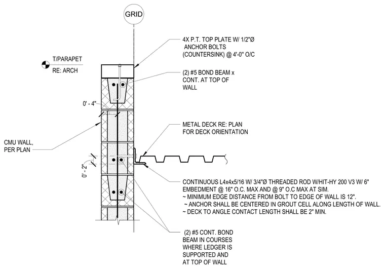
This assembly features a continuous L4x4x5/16 steel angle ledger supporting a metal deck, anchored to a concrete masonry unit wall using 3/4-inch diameter threaded rods with Hilti HIT-HY 200 V3 adhesive and 6-inch embedment. The anchors are spaced at 16 inches on center maximum, with 9 inches on center at similar conditions, and must be centered in the grout cell with a minimum 12-inch edge distance. The metal deck requires a minimum 2-inch contact length with the angle. The wall is reinforced with two number 5 continuous bond beam bars at the ledger location and at the top of the wall. A 4x pressure-treated top plate is secured to the top of the wall with 1/2-inch diameter countersunk anchor bolts spaced at 4 feet on center.
GRID GRID CMU WALL, PER PLAN 0' - 4" CONTINUOUS L4x4x5/16 W/ 3/4"Ø THREADED ROD W/HIT-HY 200 V3 W/ 6" EMBEDMENT @ 16" O.C. MAX AND @ 9" O.C MAX AT SIM. ~ MINIMUM EDGE DISTANCE FROM BOLT TO EDGE OF WALL IS 12". ~ ANCHOR SHALL BE CENTERED IN GROUT CELL ALONG LENGTH OF WALL. ~ DECK TO ANGLE CONTACT LENGTH SHALL BE 2" MIN. METAL DECK RE: PLAN FOR DECK ORIENTATION T/PARAPET RE: ARCH 4X P.T. TOP PLATE W/ 1/2''Ø ANCHOR BOLTS (COUNTERSINK) @ 4'-0'' O/C (2) #5 CONT. BOND BEAM IN COURSES WHERE LEDGER IS 0' - 2" (2) #5 BOND BEAM x CONT. AT TOP OF WALL METAL DECK RE: PLAN STEEL BEAM RE: PLAN STEEL BEAM RE: PLAN TYP. 0' - 4" TYP. 0' - 2" TYP. 0' - 0 1/2" 0' - 2"0' - 2 1/2" 3/8" THRU PLATE W/(5)-1" Ø BOLTS. TYP HSS COLUMN RE: PLAN
Members view this detail in full resolution, download the CAD files (SVG, PDF), and can adapt it in the built-in CAD editor — export DXF, DWG, or PDF.
Start membership