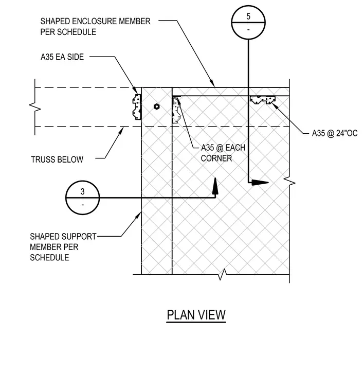
A truss corner connection utilizes shaped support and enclosure members sized per schedule. Framing clips are attached to each side and at each corner of the assembly, with additional clips spaced at twenty-four inches on center. The underlying truss positioned below is anchored by the connecting hardware.
SHAPED ENCLOSURE MEMBER PER SCHEDULE SHAPED SUPPORT MEMBER PER SCHEDULE A35 EA SIDE A35 @ EACH CORNER TRUSS BELOW A35 @ 24"OC 5 - PLAN VIEW 3 -
Members view this detail in full resolution, download the CAD files (SVG, PDF), and can adapt it in the built-in CAD editor — export DXF, DWG, or PDF.
Start membership