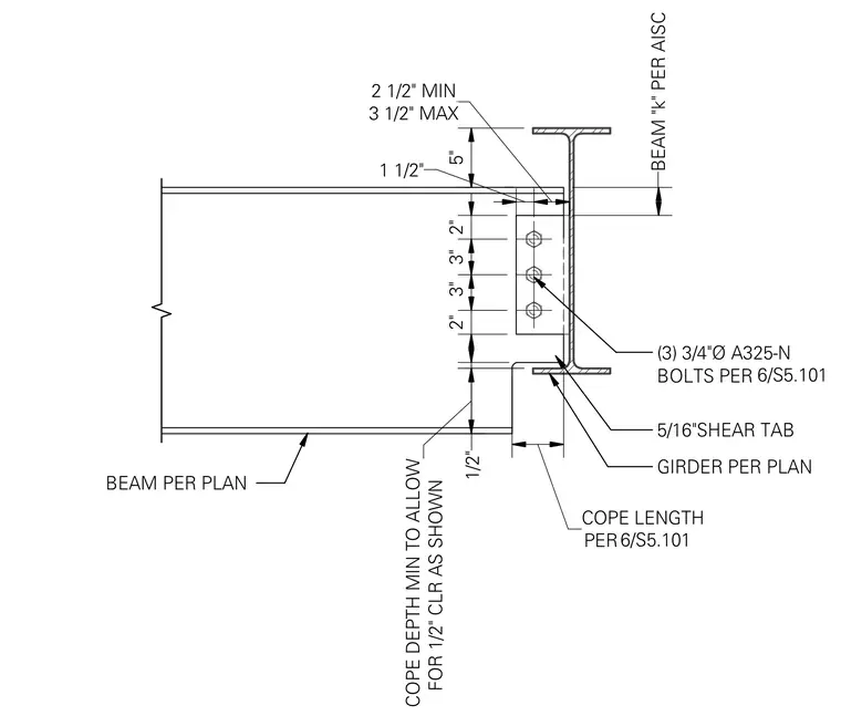
A steel framing beam connects to the web of a supporting girder using a single plate shear tab welded to the girder and bolted to the supported beam web with three three-quarter-inch diameter A325-N bolts. The top flange of the beam is coped to clear the girder flange, maintaining a minimum half-inch clearance and a specified cope length and depth per the structural plans. A five-sixteenth-inch fillet weld secures the shear tab to the girder, while vertical and horizontal dimensions establish standard clearances, edge distances, and beam set-back limits relative to the AISC beam dimension "k".
BEAM PER PLAN 1 1/2" 3 1/2" MAX 2 1/2" MIN 2" 3" 3" 2" BEAM "k" PER AISC GIRDER PER PLAN (3) 3/4"Ø A325-N BOLTS PER 6/S5.101 5/16"SHEAR TAB PER COPE LENGTH 6/S5.101 5" FOR 1/2" CLR AS SHOWN COPE DEPTH MIN TO ALLOW 1/2"
Members view this detail in full resolution, download the CAD files (SVG, PDF), and can adapt it in the built-in CAD editor — export DXF, DWG, or PDF.
Start membership