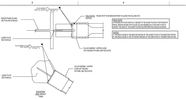
The loose-shipped collar assembly slides over the brace connection after the brace is fully welded to the gusset plates at both ends. A temporary re-bar stop is removed prior to sliding the collar assembly into position against the edge of the gusset plates. Five-sixteenths inch fillet welds connect the collar assembly to the gusset plate and core plate, with optional placement on the near or far side of the gusset plate and the top or bottom of the core plate at the erector's option. The braced frame column and gusset plates are sized per plan and schedule.
B. THIS WELD CAN BE AT THE TOP OR BOTTOM SIDE OF THE CORE PLATE AT THE ERECTOR'S OPTION. A. THIS WELD CAN BE AT THE NEAR OR FAR SIDE OF THE GUSSET PLATE AT THE ERECTOR'S OPTION. COLLAR ASSEMBLY. SHIPPED LOOSE (NOT WELDED) COLLAR ASSEMBLY. SHIPPED LOOSE (NOT WELDED) WITH BRB. (SEE FIELD NOTE) AFTER BRB IS IN PLACE AND FULLY WELDED TO THE GUSSET PLATES AT BOTH ENDS OF BRACE, REMOVE RE-BAR STOP & SLIDE COLLAR ASSEMBLIES AT EACH END TO BE UP GUSSET PLATE, BRACED FRAME COLUMN, GUSSET PLATE ~ RE-BAR STOP TO BE REMOVED PRIOR TO SLIDING THE COLLARS INTO POSITION. ELEVATION VIEW (SINGLE TUBE) NOTES: FIELD NOTE: FIELD NOTE: SEE PLAN AND SCHEDULE 5/16 2 WITH BRB. (SEE FIELD NOTE) 5/16 2 COLLAR ASSEMBLY TO CORE PLATE. (SEE NOTE B) SEE SCHEDULE SEE SCHEDULE COLLAR ASSEMBLY TO GUSSET PLATE. (SEE NOTE A) AGAINST THE EDGE OF THE GUSSET PLATES AND PERFORM FIELD WELDS AS SHOWN. 3 4
Members view this detail in full resolution, download the CAD files (SVG, PDF), and can adapt it in the built-in CAD editor — export DXF, DWG, or PDF.
Start membership