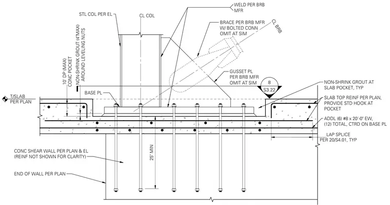
A steel column sits on a base plate anchored by multiple anchor bolts extending twenty-five inches minimum into the concrete shear wall below. A gusset plate and brace per the buckling-restrained brace manufacturer connect to the assembly, with welds and bolted connections as specified. A ten-inch maximum concrete pocket surrounds the leveling nuts, filled with non-shrink grout up to four inches maximum. Additional reinforcing steel including six number eight bars by twenty feet long each way are centered on the base plate with standard hooks at the pocket, supplemented by lap splices per plan.
CL BRB T/SLAB PER PLAN CL COL 25" MIN SLAB TOP REINF PER PLAN, PROVIDE STD HOOK AT POCKET ADDL (6) #8 x 20'-0" EW, (12) TOTAL, CTRD ON BASE PL S3.22 8 PER 20/S4.01, TYP LAP SPLICE GUSSET PL PER BRB MFR OMIT AT SIM BRACE PER BRB MFR W/ BOLTED CONN OMIT AT SIM CONC POCKET 10' DP (MAX) AROUND LEVELING NUTS NON-SHRINK GROUT (4"MAX) STL COL PER EL BASE PL WELD PER BRB MFR CONC SHEAR WALL PER PLAN & EL (REINF NOT SHOWN FOR CLARITY) NON-SHRINK GROUT AT SLAB POCKET, TYP END OF WALL PER PLAN
Members view this detail in full resolution, download the CAD files (SVG, PDF), and can adapt it in the built-in CAD editor — export DXF, DWG, or PDF.
Start membership