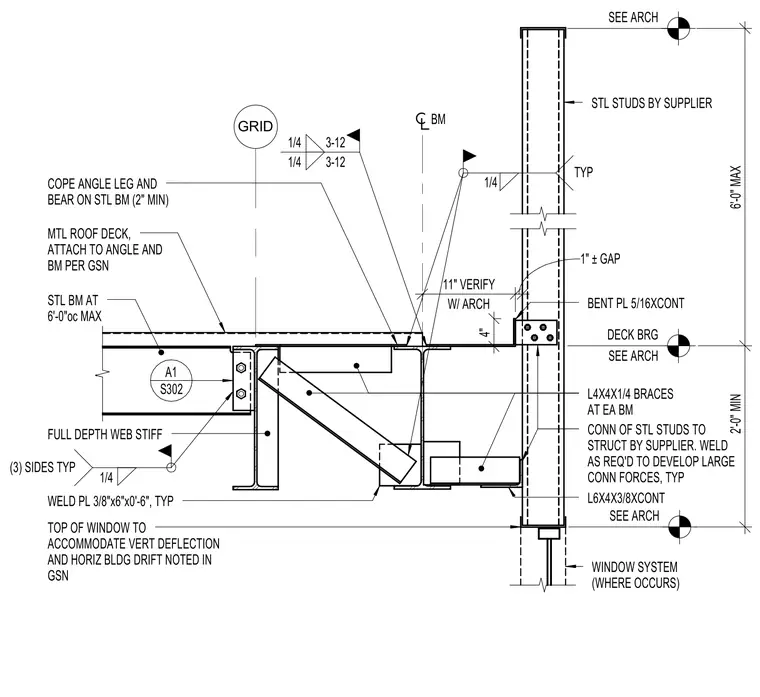
A steel beam is spaced at a maximum of six feet on center with a full-depth web stiffener and three-eighths by six by six-inch welded plate typical. A metal roof deck attaches to the supporting angle and steel beam per general structural notes. The structural steel studs connect to the structure via continuous bent plates and continuous six-by-four-by-three-eighths-inch angles, with L4x4x1/4 braces provided at each beam. A cope angle leg bears on the steel beam with a two-inch minimum bearing length. The window system accommodates vertical deflection and horizontal building drift as noted in general structural notes, maintaining a one-inch plus or minus gap verified with architectural drawings.
4" S302 A1 BM GRID W/ ARCH 11" VERIFY 1" ± GAP SEE ARCH SEE ARCH DECK BRG SEE ARCH 2'-0" MIN 6'-0" MAX STL BM AT 6'-0"oc MAX FULL DEPTH WEB STIFF WELD PL 3/8"x6"x0'-6", TYP TOP OF WINDOW TO ACCOMMODATE VERT DEFLECTION AND HORIZ BLDG DRIFT NOTED IN GSN MTL ROOF DECK, ATTACH TO ANGLE AND BM PER GSN L4X4X1/4 BRACES AT EA BM WINDOW SYSTEM (WHERE OCCURS) L6X4X3/8XCONT CONN OF STL STUDS TO STRUCT BY SUPPLIER. WELD AS REQ'D TO DEVELOP LARGE CONN FORCES, TYP BENT PL 5/16XCONT STL STUDS BY SUPPLIER COPE ANGLE LEG AND BEAR ON STL BM (2" MIN) (3) SIDES TYP 1/4 1/4 1/4 3-12 3-12 TYP 1/4
Members view this detail in full resolution, download the CAD files (SVG, PDF), and can adapt it in the built-in CAD editor — export DXF, DWG, or PDF.
Start membership