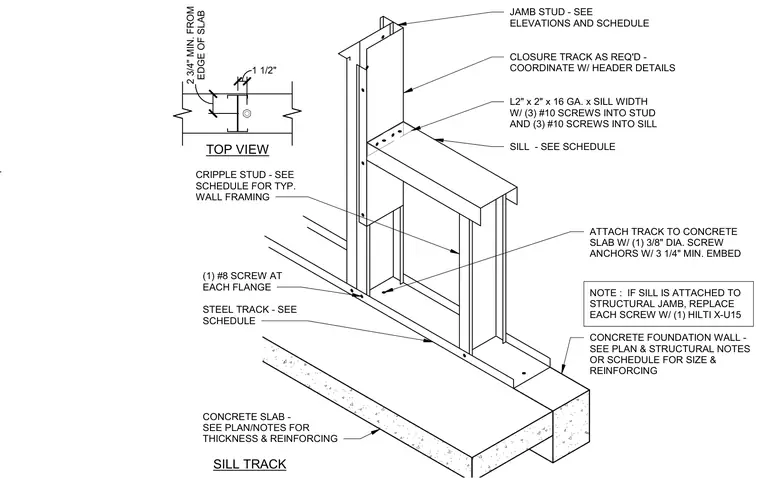
A cold-formed steel framing connection at a window opening sill bears on a concrete foundation wall and floor slab. The steel track is anchored to the concrete slab using three-eighths-inch diameter screw anchors with a three-and-a-quarter-inch minimum embedment, maintaining a two-and-three-quarters-inch minimum edge distance. A two-inch by two-inch by sixteen-gauge angle cut to the sill width connects the sill to the jamb stud using three number ten screws into the stud and three number ten screws into the sill. Cripple studs and jamb studs tie into the assembly per the project schedule, with individual screw connections securing the track flanges. Where the sill attaches directly to a structural jamb, each screw is replaced with one Hilti X-U15 fastener. Closure tracks are provided at the head and sill as required and coordinated with adjacent header details.
BOTTOM AT SILL TRACK NOTE : IF SILL IS ATTACHED TO STRUCTURAL JAMB, REPLACE EACH SCREW W/ (1) HILTI X-U15 CRIPPLE STUD - SEE SCHEDULE FOR TYP. WALL FRAMING STEEL TRACK - SEE SCHEDULE JAMB STUD - SEE ELEVATIONS AND SCHEDULE L2" x 2" x 16 GA. x SILL WIDTH W/ (3) #10 SCREWS INTO STUD AND (3) #10 SCREWS INTO SILL SILL - SEE SCHEDULE TOP VIEW (1) #8 SCREW AT EACH FLANGE ATTACH TRACK TO CONCRETE SLAB W/ (1) 3/8" DIA. SCREW ANCHORS W/ 3 1/4" MIN. EMBED EDGE OF SLAB 2 3/4" MIN. FROM CLOSURE TRACK AS REQ'D - COORDINATE W/ HEADER DETAILS 1 1/2" CONCRETE FOUNDATION WALL - SEE PLAN & STRUCTURAL NOTES OR SCHEDULE FOR SIZE & REINFORCING CONCRETE SLAB - SEE PLAN/NOTES FOR THICKNESS & REINFORCING
Members view this detail in full resolution, download the CAD files (SVG, PDF), and can adapt it in the built-in CAD editor — export DXF, DWG, or PDF.
Start membership