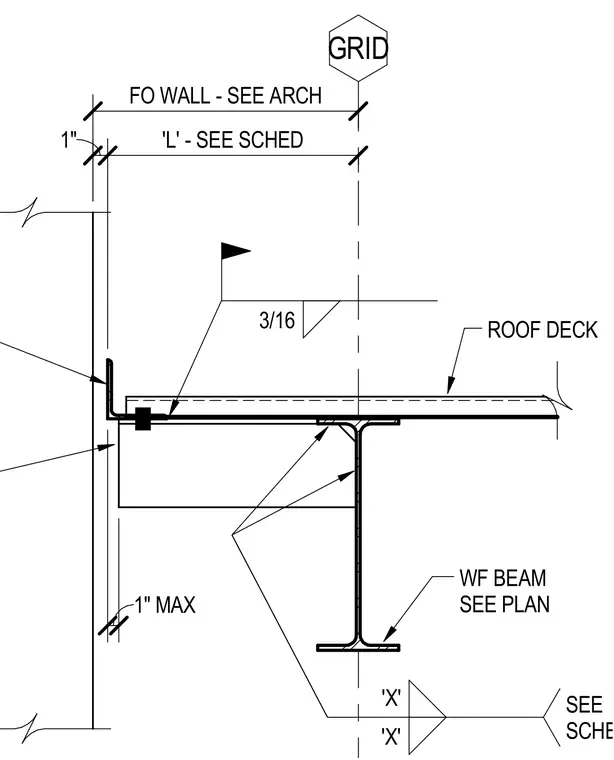
A roof deck runs perpendicular to the edge condition, terminating near a finished exterior wall referenced per architectural drawings. A wide flange beam, sized per plan, supports the roof deck assembly along a grid line. An angle iron, sized per schedule, is anchored near the wall with a maximum one inch clearance. A three-sixteenths inch fillet weld secures the assembly components. Connection details reference standard structural schedules and architectural wall layouts.
'X' 'X' SEE SCHED ROOF DECK WF BEAM SEE PLAN GRID FO WALL - SEE ARCH 1" 'L' - SEE SCHED 3/16 1" MAX
Members view this detail in full resolution, download the CAD files (SVG, PDF), and can adapt it in the built-in CAD editor — export DXF, DWG, or PDF.
Start membership