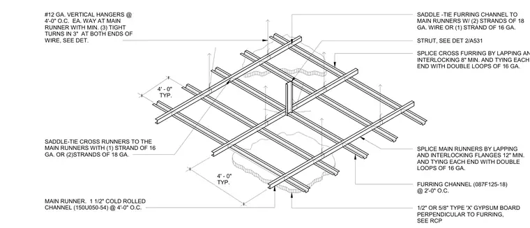
Main runners utilize one and a half inch cold-rolled channels spaced at four feet on center, supported by twelve gauge vertical wire hangers spaced at four feet on center each way with a minimum of three tight turns in three inches at both ends. Furring channels are spaced at two feet on center and tied to main runners with either two strands of eighteen gauge wire or one strand of sixteen gauge wire. Cross furring and main runners are spliced by lapping and interlocking with specified minimum lengths and tied with double loops of sixteen gauge wire. One-half inch or five-eighths inch Type X gypsum board is fastened perpendicular to the furring channels.
#12 GA. VERTICAL HANGERS @ 4'-0" O.C. EA. WAY AT MAIN RUNNER WITH MIN. (3) TIGHT TURNS IN 3" AT BOTH ENDS OF WIRE, SEE DET. SPLICE CROSS FURRING BY LAPPING AND INTERLOCKING 8" MIN. AND TYING EACH END WITH DOUBLE LOOPS OF 16 GA. SADDLE -TIE FURRING CHANNEL TO MAIN RUNNERS W/ (2) STRANDS OF 18 GA. WIRE OR (1) STRAND OF 16 GA. SPLICE MAIN RUNNERS BY LAPPING AND INTERLOCKING FLANGES 12" MIN. AND TYING EACH END WITH DOUBLE LOOPS OF 16 GA. SADDLE-TIE CROSS RUNNERS TO THE MAIN RUNNERS WITH (1) STRAND OF 16 GA. OR (2)STRANDS OF 18 GA. STRUT, SEE DET 2/A531 MAIN RUNNER. 1 1/2" COLD ROLLED CHANNEL (150U050-54) @ 4'-0" O.C. 1/2" OR 5/8" TYPE 'X' GYPSUM BOARD PERPENDICULAR TO FURRING, SEE RCP FURRING CHANNEL (087F125-18) @ 2'-0" O.C. 4' - 0" TYP. 4' - 0" TYP.
Members view this detail in full resolution, download the CAD files (SVG, PDF), and can adapt it in the built-in CAD editor — export DXF, DWG, or PDF.
Start membership