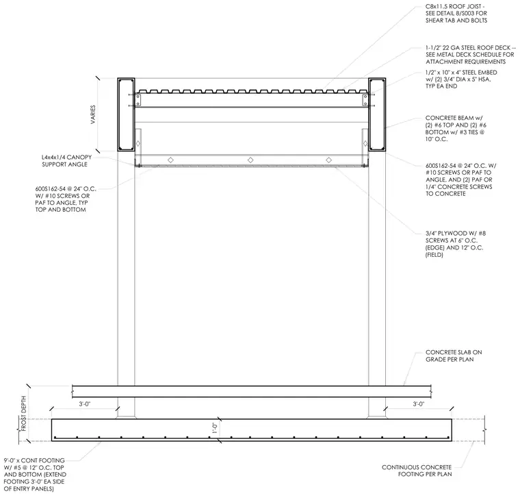
This cross section details a structural canopy and vestibule entrance assembly supported by a continuous concrete footing measuring nine feet wide with top and bottom reinforcing bars. The reinforced concrete beams feature top and bottom reinforcing bars with ties, anchoring steel embed plates with heavy-duty sleeve anchors at each end. A C8x11.5 steel roof joist supports a one-and-a-half-inch twenty-two gauge steel roof deck and framing. Cold-formed steel stud framing connects to the canopy support angle using screws or powder-actuated fasteners, and sheathing is applied using plywood panels fastened at the edges and field.
FROST DEPTH VARIES L4x4x1/4 CANOPY SUPPORT ANGLE CONCRETE SLAB ON GRADE PER PLAN CONTINUOUS CONCRETE FOOTING PER PLAN 600S162-54 @ 24" O.C. W/ #10 SCREWS OR PAF TO ANGLE, AND (2) PAF OR 1/4" CONCRETE SCREWS TO CONCRETE CONCRETE BEAM w/ (2) #6 TOP AND (2) #6 BOTTOM w/ #3 TIES @ 10" O.C. 1-1/2" 22 GA STEEL ROOF DECK -- SEE METAL DECK SCHEDULE FOR ATTACHMENT REQUIREMENTS 1/2" x 10" x 4" STEEL EMBED w/ (2) 3/4" DIA x 5" HSA, TYP EA END C8x11.5 ROOF JOIST - SEE DETAIL 8/S003 FOR SHEAR TAB AND BOLTS 600S162-54 @ 24" O.C. W/ #10 SCREWS OR PAF TO ANGLE, TYP TOP AND BOTTOM 3/4" PLYWOOD W/ #8 SCREWS AT 6" O.C. (EDGE) AND 12" O.C. (FIELD) 9'-0" x CONT FOOTING W/ #5 @ 12" O.C. TOP AND BOTTOM (EXTEND FOOTING 3'-0" EA SIDE OF ENTRY PANELS) 3'-0" 3'-0" 1'-0"
Members view this detail in full resolution, download the CAD files (SVG, PDF), and can adapt it in the built-in CAD editor — export DXF, DWG, or PDF.
Start membership