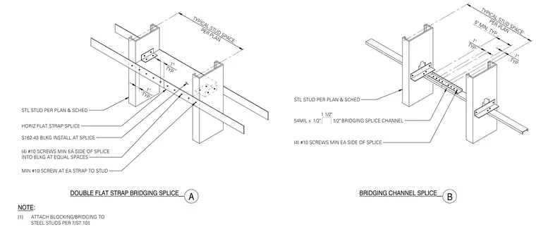
This isometric detail shows typical steel stud wall bridging splices using cold-formed steel framing. The assembly features steel studs sized per plan and schedule connected by horizontal flat strap splices or bridging channel splices. Blocking is installed at the splice location using S162-43 members attached with a minimum of four number 10 screws on each side of the splice at equal spaces. Additional number 10 screws secure each strap to the steel stud framing.
TYPICAL STUD SPACE PER PLAN STL STUD PER PLAN & SCHED DOUBLE FLAT STRAP BRIDGING SPLICE A HORIZ FLAT STRAP SPLICE S162-43 BLKG INSTALL AT SPLICE (4) #10 SCREWS MIN EA SIDE OF SPLICE INTO BLKG AT EQUAL SPACES MIN #10 SCREW AT EA STRAP TO STUD BRIDGING CHANNEL SPLICE NOTE: [1] ATTACH BLOCKING/BRIDGING TO STEEL STUDS PER . STL STUD PER PLAN & SCHED 54MIL x BRIDGING SPLICE CHANNEL (4) #10 SCREWS MIN EA SIDE OF SPLICE TYPICAL STUD SPACE PER PLAN 5" MIN, TYP 1" TYP 1" TYP 1" TYP 1" TYP B 1 1/2" 1/2" 1/2" 7/S7.101
Members view this detail in full resolution, download the CAD files (SVG, PDF), and can adapt it in the built-in CAD editor — export DXF, DWG, or PDF.
Start membership