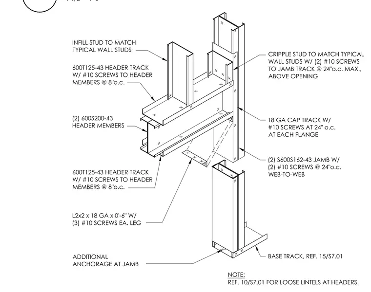
The cold-formed steel door jamb consists of double S600S162-43 studs fastened web-to-web with two number 10 screws spaced at twenty-four inches on center, fitted with an eighteen gauge cap track secured with number 10 screws at each flange. The double 600S200-43 header members are sandwiched between top and bottom 600T125-43 header tracks fastened with number 10 screws at eight inches on center. Cripple studs matching typical wall studs connect to the jamb track above the opening at a maximum spacing of twenty-four inches on center, while infill studs match typical wall framing. A two-inch by two-inch by eighteen gauge by six-inch clip angle with three number 10 screws on each leg ties the header assembly to the jamb. Additional anchorage is provided at the jamb base track per reference drawings.
ADDITIONAL ANCHORAGE AT JAMB BASE TRACK, REF. 15/S7.01 (2) S600S162-43 JAMB W/ (2) #10 SCREWS @ 24"o.c. WEB-TO-WEB 18 GA CAP TRACK W/ #10 SCREWS AT 24" o.c. AT EACH FLANGE CRIPPLE STUD TO MATCH TYPICAL WALL STUDS W/ (2) #10 SCREWS TO JAMB TRACK @ 24"o.c. MAX., ABOVE OPENING L2x2 x 18 GA x 0'-6" W/ (3) #10 SCREWS EA. LEG (2) 600S200-43 HEADER MEMBERS 600T125-43 HEADER TRACK W/ #10 SCREWS TO HEADER MEMBERS @ 8"o.c. 600T125-43 HEADER TRACK W/ #10 SCREWS TO HEADER MEMBERS @ 8"o.c. INFILL STUD TO MATCH TYPICAL WALL STUDS NOTE: REF. 10/S7.01 FOR LOOSE LINTELS AT HEADERS. 12 1 1/2" = 1'-0"
Members view this detail in full resolution, download the CAD files (SVG, PDF), and can adapt it in the built-in CAD editor — export DXF, DWG, or PDF.
Start membership