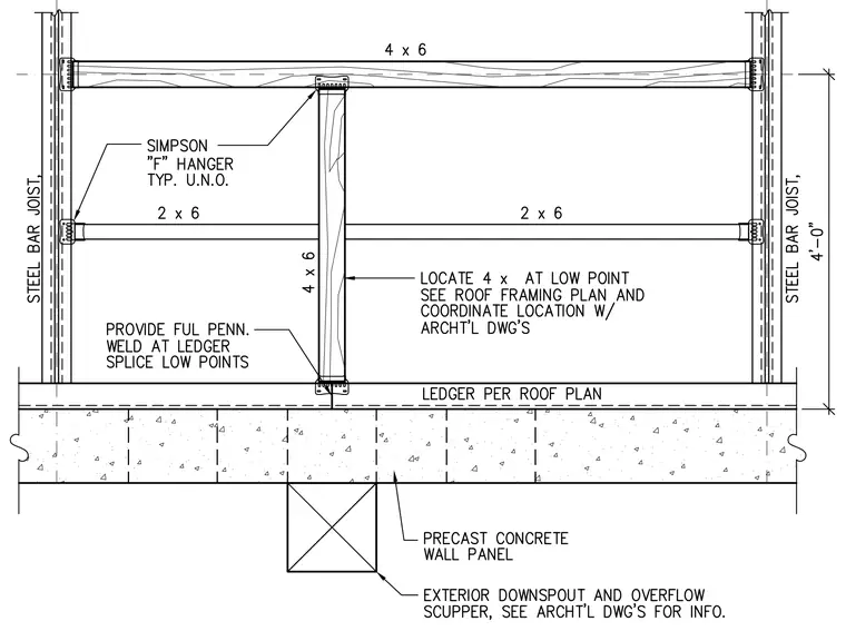
Wood framing components support roof drainage areas utilizing four-by-six and two-by-six members connected with Simpson F-type hangers typically unless noted otherwise. Four-by members are located at low points per the roof framing plan and coordinated with architectural drawings. A ledger per the roof plan bears on a precast concrete wall panel, requiring full penetration welds at ledger splice low points. Steel bar joists frame into the assembly at the sides, while exterior downspouts and overflow scuppers are positioned below as detailed in architectural drawings.
Members view this detail in full resolution, download the CAD files (SVG, PDF), and can adapt it in the built-in CAD editor — export DXF, DWG, or PDF.
Start membership