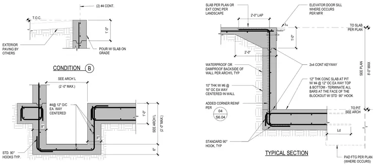
A standard concrete elevator pit with reinforced walls and base slab. The ten-inch thick pit walls feature number six reinforcing bars spaced at sixteen inches on center each way, centered within the wall. The twelve-inch thick concrete slab at the pit incorporates number four bars at twelve inches on center each way at both top and bottom, terminating at the blockout face with standard ninety-degree hooks. A continuous two-by-four keyway is provided at the wall-to-slab construction joint, and the exterior of the wall receives waterproofing or dampproofing per architectural drawings. At the top of the pit wall, an elevator door sill is detailed with slab connections and lap splices per plan.
CONDITION T.O.C. EXTERIOR PAVING BY OTHERS (2) #4 CONT. POUR W/ SLAB ON GRADE STD. 90° HOOKS TYP. #4@ 12" O/C EA. WAY CENTERED TYPICAL SECTION TO SLAB PER PLAN TO PIT SEE ARCH ELEVATOR DOOR SILL WHERE OCCURS PER MFR 10" THK W/ #6 @ 16" OC EA WAY CENTERED IN WALL WATERPROOF OR DAMPROOF BACKSIDE OF WALL PER ARCHI'L TYP 2x4 CONT KEYWAY 12" THK CONC SLAB AT PIT W/ #4 @ 12" OC EA WAY TOP & BOTTOM - TERMINATE ALL BARS AT THE FACE OF THE BLOCKOUT W/ STD 90° HOOK STANDARD 90° HOOK, TYP 8'-0" MAX SEE PLAN 2'-0" LAP 1'-0" SLAB PER PLAN OR EXT CONC PER LANDSCAPE 2" Ld PAD FTG PER PLAN (WHERE OCCURS) ADDED CORNER REINF PER B 2'-0" 8" (2´-0" MAX.) SEE ARCH´L 1'-0" 6" (2´-0" MAX.) SEE ARCH´L 8" 1´-0" 04 S6.04
Members view this detail in full resolution, download the CAD files (SVG, PDF), and can adapt it in the built-in CAD editor — export DXF, DWG, or PDF.
Start membership