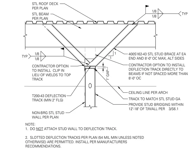
Top-of-wall bracing for a non-bearing steel stud wall intersecting an overhead steel beam and steel roof deck. Diagonal 400S162-43 steel stud braces are installed at each end and spaced at a maximum of eight feet on center along alternate sides, welded to the steel beam with one-eighth-inch fillet welds. A T200-43 deflection track with a minimum two-inch flange is provided at the top of the non-bearing steel stud wall, maintaining a one-inch gap below the structural framing to allow for vertical deflection. A contractor option permits installing clips in lieu of welds to the top track, or installing deflection tracks directly to beams if spaced no more than eight feet on center. Stud bridging is required within twelve to eighteen inches of the top of the wall. General notes specify that the stud wall must not be rigidly attached to the deflection track, and that slotted deflection tracks of at least fifty-four mil thickness are permitted per manufacturer recommendations.
NON-BRG STL STUD WALL PER PLAN 400S162-43 STL STUD BRACE AT EA END AND 8'-0" OC MAX, ALT SIDES STL ROOF DECK PER PLAN STL BEAM PER PLAN T200-43 DEFLECTION TRACK (MIN 2" FLG) 1 1 CEILING LINE PER ARCH CONTRACTOR OPTION TO INSTALL DEFLECTION TRACK DIRECTLY TO BEAMS IF NOT SPACED MORE THAN 8'-0" OC CONTRACTOR OPTION TO INSTALL CLIP IN LIEU OF WELDS TO TOP TRACK NOTE: 1. DO NOT ATTACH STUD WALL TO DEFLECTION TRACK. 2. SLOTTED DEFLECTION TRACKS PER PLAN (54 MIL MIN UNLESS NOTED OTHERWISE) ARE PERMITTED. INSTALL PER MANUFACTURERS RECOMMENDATIONS. PROVIDE STUD BRIDGING WITHIN 12"-18" OF T/WALL PER TRACK TO MATCH STL STUD GA 1/8 1/8 TYP 1/8 1/8 TYP 1" GAP 3/S6.1
Members view this detail in full resolution, download the CAD files (SVG, PDF), and can adapt it in the built-in CAD editor — export DXF, DWG, or PDF.
Start membership