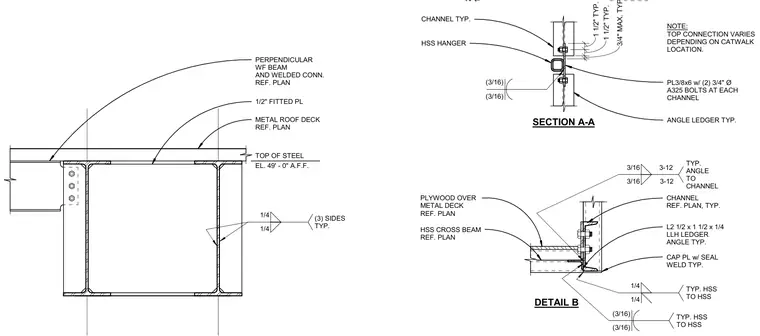
Structural connections for a stage left fly gallery at an elevation of 49 feet above finished floor incorporate hollow structural section hangers, channel ledgers, and a wide-flange beam framing system. Section A-A contains a hollow structural section hanger secured between channel ledgers using a 3/8-inch by 6-inch plate with two 3/4-inch diameter ASTM A325 bolts at each channel. Detail B includes a plywood over metal roof deck supported by an HSS cross beam, connected to a channel ledger via a 2-1/2 inch by 1-1/2 inch by 1/4-inch angle ledger with 3/16-inch welds spaced at 12 inches. A fitted 1/2-inch plate connects the perpendicular wide-flange beam to the supporting girder with three-sided 1/4-inch fillet welds. Additional cap plates receive seal welds typical across hollow structural section connections.
NOTE: TOP CONNECTION VARIES DEPENDING ON CATWALK LOCATION. 2 1/2" 1 1/2" SECTION A-A 1 1/2" TYP. 1 1/2" TYP. 3/4" MAX. TYP. (3/16) (3/16) PL3/8x6 w/ (2) 3/4" Ø A325 BOLTS AT EACH CHANNEL ANGLE LEDGER TYP. CHANNEL TYP. HSS HANGER PLYWOOD OVER METAL DECK REF. PLAN CHANNEL REF. PLAN, TYP. HSS CROSS BEAM REF. PLAN CAP PL w/ SEAL WELD TYP. L2 1/2 x 1 1/2 x 1/4 LLH LEDGER ANGLE TYP. 1/4 1/4 TYP. HSS TO HSS (3/16) (3/16) TYP. HSS TO HSS 3/16 3-12 3/16 3-12 TYP. ANGLE TO CHANNEL DETAIL B PERPENDICULAR WF BEAM AND WELDED CONN. REF. PLAN 1/4 1/4 (3) SIDES TYP. 1/2" FITTED PL METAL ROOF DECK REF. PLAN TOP OF STEEL EL. 49' - 0" A.F.F.
Members view this detail in full resolution, download the CAD files (SVG, PDF), and can adapt it in the built-in CAD editor — export DXF, DWG, or PDF.
Start membership