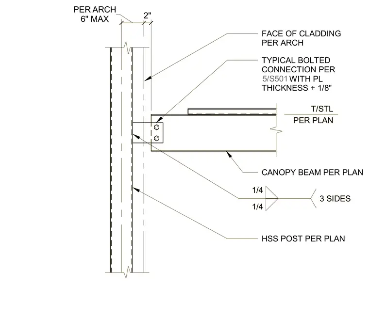
A canopy beam connects to a hollow structural section post using a typical bolted connection with a plate thickness plus one-eighth inch. The connection assembly incorporates fillet welds on three sides as specified. The face of the cladding is positioned at a designated distance per the architectural drawings, with a two-inch clearance maintained from the structural post. Top of steel elevations and member sizes are sized per plan.
T/STL PER PLAN 1/4 1/4 3 SIDES FACE OF CLADDING PER ARCH 6" MAX PER ARCH 2" HSS POST PER PLAN CANOPY BEAM PER PLAN TYPICAL BOLTED CONNECTION PER WITH PL THICKNESS + 1/8" 5/S501 T/STL PER PLAN 1/4 1/4 3 SIDES FACE OF CLADDING PER ARCH 6" MAX PER ARCH 2" HSS POST PER PLAN CANOPY BEAM PER PLAN TYPICAL BOLTED CONNECTION PER WITH PL THICKNESS + 1/8" 5/S501
Members view this detail in full resolution, download the CAD files (SVG, PDF), and can adapt it in the built-in CAD editor — export DXF, DWG, or PDF.
Start membership