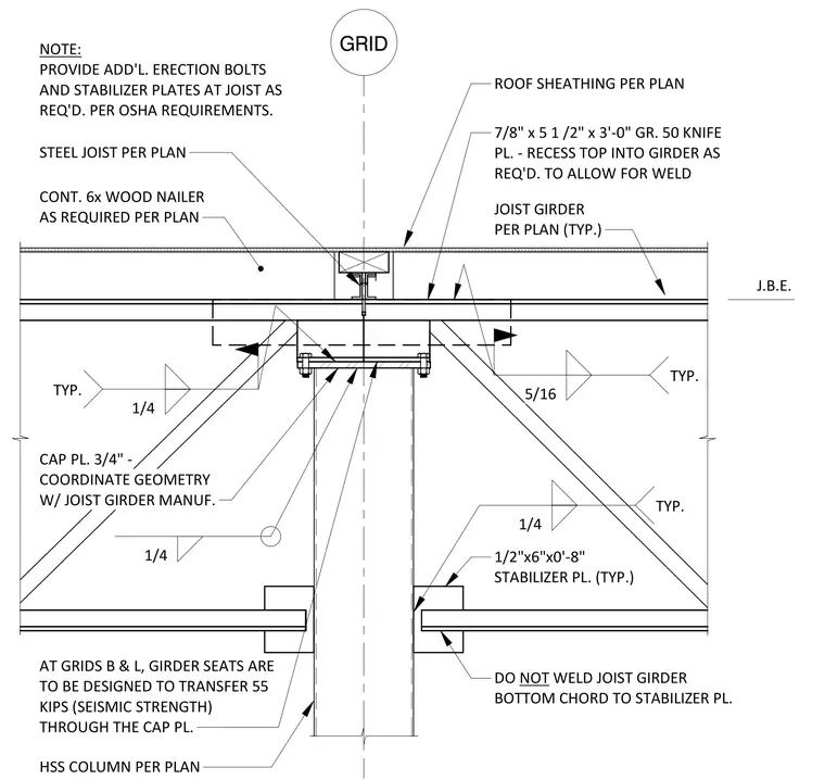
The joist girder is supported by a hollow structural section column topped with a 3/4-inch thick cap plate, with geometry coordinated with the joist girder manufacturer. A 7/8-inch by 5 1/2-inch by 3-foot Grade 50 knife plate is recessed into the top of the girder to facilitate a 1/4-inch typical fillet weld. The girder is stabilized by 1/2-inch by 6-inch by 8-inch stabilizer plates welded to the column, though the bottom chord of the joist girder must remain unwelded to these plates. Additional erection bolts and stabilizer plates are provided at the joist as required by OSHA. A continuous 6x wood nailer is installed above the joist girder to support the roof sheathing.
3 NOTE: PROVIDE ADD'L. ERECTION BOLTS AND STABILIZER PLATES AT JOIST AS REQ'D. PER OSHA REQUIREMENTS. J.B.E. JOIST GIRDER PER PLAN (TYP.) STEEL JOIST PER PLAN CAP PL. 3/4" - COORDINATE GEOMETRY W/ JOIST GIRDER MANUF. GRID 5/16 TYP. ROOF SHEATHING PER PLAN CONT. 6x WOOD NAILER AS REQUIRED PER PLAN 7/8" x 5 1 /2" x 3'-0" GR. 50 KNIFE PL. - RECESS TOP INTO GIRDER AS REQ'D. TO ALLOW FOR WELD 1/4 TYP.
Members view this detail in full resolution, download the CAD files (SVG, PDF), and can adapt it in the built-in CAD editor — export DXF, DWG, or PDF.
Start membership