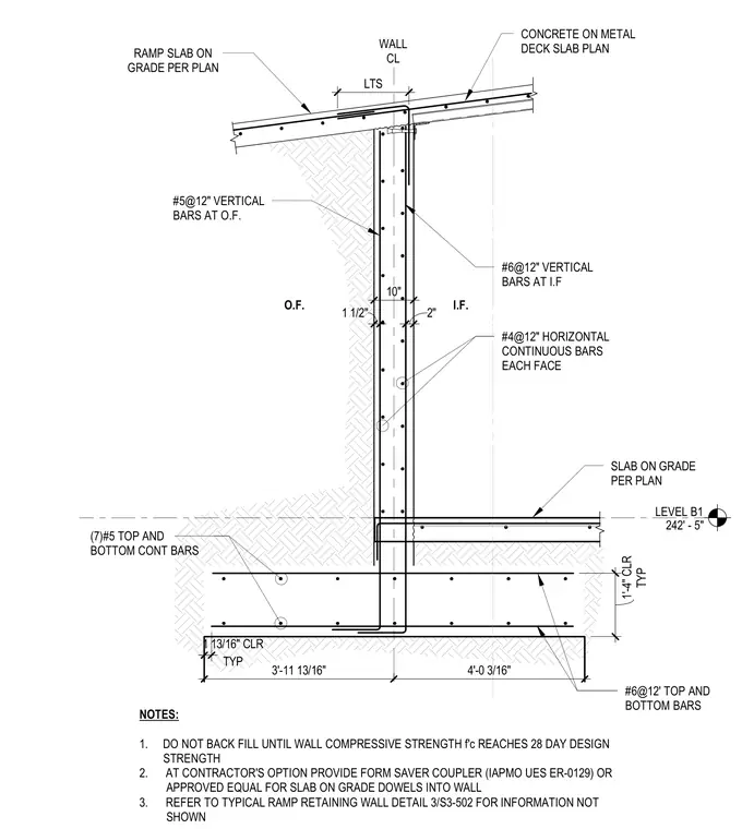
A concrete ramp retaining wall features a ten-inch thick stem wall interfacing with a concrete slab-on-grade and a concrete on metal deck slab. The ten-inch wall includes number five vertical bars at twelve inches on center on the outside face, number six vertical bars at twelve inches on center on the inside face, and number four horizontal continuous bars on each face. The footing contains seven number five top and bottom continuous bars on the inside face and number six bars top and bottom at twelve inches on center typical. Level B1 is established at elevation 242 feet five inches. Notes specify that backfilling must not occur until the wall compressive strength reaches the twenty-eight-day design strength, and contractors have the option to provide a form saver coupler or approved equal for slab-on-grade dowels into the wall.
LEVEL B1 242' - 5" NOTES: 1. DO NOT BACK FILL UNTIL WALL COMPRESSIVE STRENGTH f'c REACHES 28 DAY DESIGN STRENGTH 2. AT CONTRACTOR'S OPTION PROVIDE FORM SAVER COUPLER (IAPMO UES ER-0129) OR APPROVED EQUAL FOR SLAB ON GRADE DOWELS INTO WALL 3. REFER TO TYPICAL RAMP RETAINING WALL DETAIL 3/S3-502 FOR INFORMATION NOT SHOWN 1 1/2" 2" 10" 3'-11 13/16" 4'-0 3/16" WALL CL RAMP SLAB ON GRADE PER PLAN #5@12" VERTICAL BARS AT O.F. SLAB ON GRADE PER PLAN #4@12" HORIZONTAL CONTINUOUS BARS EACH FACE #6@12" VERTICAL BARS AT I.F CONCRETE ON METAL DECK SLAB PLAN TYP 1'-4" CLR #6@12' TOP AND BOTTOM BARS TYP 1 13/16" CLR (7)#5 TOP AND BOTTOM CONT BARS I.F. O.F. LTS
Members view this detail in full resolution, download the CAD files (SVG, PDF), and can adapt it in the built-in CAD editor — export DXF, DWG, or PDF.
Start membership