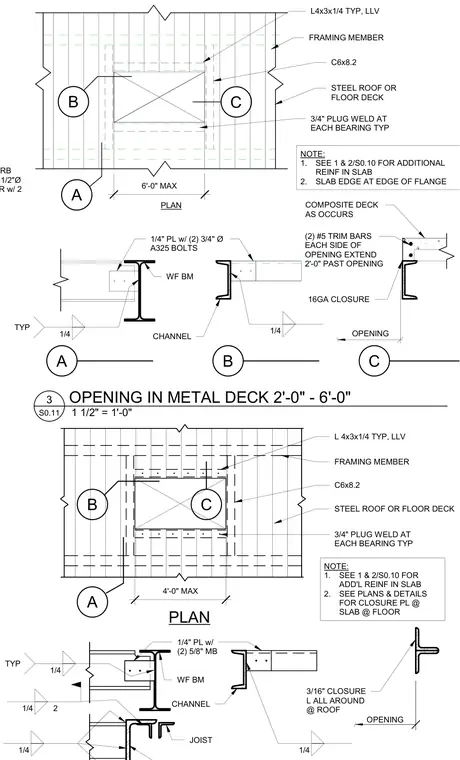
Framing details illustrate floor and roof penetrations through steel deck and concrete slabs, framed with channel members and supported by wide-flange beams or joists. Openings are reinforced with two number five trim bars on each side extending two feet past the opening, alongside a quarter-inch plate connected with two three-quarter-inch or five-eighth-inch bolts. Additional support utilizes four-by-three-by-quarter-inch angle sections typically with long legs vertical, and three-quarter-inch plug welds at each deck bearing. Closure angles of sixteen-gauge or three-sixteenth-inch material seal the perimeter, while mechanical curbs anchor with half-inch expansion anchors at each corner.
MECHANICAL RAISED CURB ATTACH TO SUPPORT w/ 1/2"Ø EXP ANCHOR EA CORNER w/ 2 L4x3x1/4 TYP, LLV FRAMING MEMBER C6x8.2 STEEL ROOF OR FLOOR DECK 3/4" PLUG WELD AT EACH BEARING TYP NOTE: 1. SEE 1 & 2/S0.10 FOR ADDITIONAL REINF IN SLAB 2. SLAB EDGE AT EDGE OF FLANGE PLAN 6'-0" MAX 1/4 TYP 1/4" PL w/ (2) 3/4" Ø A325 BOLTS WF BM CHANNEL 1/4 (2) #5 TRIM BARS EACH SIDE OF OPENING EXTEND 2'-0" PAST OPENING 16GA CLOSURE OPENING A B B C C A COMPOSITE DECK AS OCCURS 4'-0" MAX PLAN L 4x3x1/4 TYP, LLV FRAMING MEMBER C6x8.2 STEEL ROOF OR FLOOR DECK 3/4" PLUG WELD AT EACH BEARING TYP NOTE: 1. SEE 1 & 2/S0.10 FOR ADD'L REINF IN SLAB 2. SEE PLANS & DETAILS FOR CLOSURE PL @ SLAB @ FLOOR 1/4" PL w/ (2) 5/8" MB WF BM CHANNEL JOIST 3/16" CLOSURE L ALL AROUND @ ROOF 1/4 1/4 1/4 2 1/4 TYP OPENING B C A 1 1/2" = 1'-0" S0.11 3 OPENING IN METAL DECK 2'-0" - 6'-0"
Members view this detail in full resolution, download the CAD files (SVG, PDF), and can adapt it in the built-in CAD editor — export DXF, DWG, or PDF.
Start membership